Recovering ATMEGA328p chip from external clock fuse set
A quick post of tragedy and triumph!
Whilst breadboarding a new project with an Atmega328p chip (the heart of some of the Arduino ecosystem), I wanted to configure the AVR "fuses" (a desperately misleading term!) in order to use an external 16 MHz crystal, rather than the default internal 8 MHz oscillator. This is straight forward and something I've done before. Using the excellent fuse calculator, I wanted to get cracking and rushed in without double checking my fuse selection. Big mistake! I saw the option "external clock" (CKSEL=0000 SUT=00), and thought "great, that's it", also unselecting the CKDIV8 option (bit 7), generates the LOW fuse = 0xC0 and the HIGH fuse = 0xD9. Two right mistakes here! First of all the small one: Selecting a box corresponds to setting the bit to '0', rather than '1', i.e. *unselecting/unticking* the CKDIV8 boxes will SET this bit as true (and divide the clock signal by 8). It can't be only me that finds it confusing, but this also is how it is specified in the datasheet! Secondly, the biggy. An external 16 MHz CRYSTAL is not an external CLOCK!Fuse reprogrammed. Chip not responding to reprogramming or crystal oscillator.
Uh-oh.
Chip bricked! :(
Fortunately it is possible to provide an external clock, reprogram the fuses and carry on with life! I suppose it's possible to use a 555 timer to provide the pulse, though I suspect their would be a frequency limit. Also it's much simpler to simply hook up an Arduino Nano to provide the external clock signal. This post also takes the same approach. The Arduino sketch is insultingly simple and looks like this:
#define output_toggle(port,pin) port ^= (1<<pin)
#define set_output(portdir,pin) portdir |= (1<<pin)
void setup() {
set_output(DDRD, 6);
}
void loop() {
while(1)
{
output_toggle(PORTD,6);
__asm__("nop\n\t");
__asm__("nop\n\t");
}
}
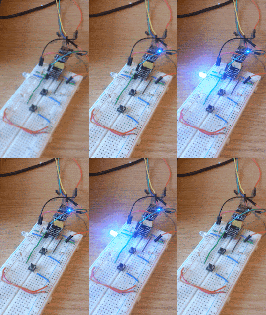
Reading The Freakin' Manual/datasheet tells us what we need to do. Power the bricked chip by the 5V and GND from the Arduino Nano, and hook up the D6 pin to the PB6 (XTAL1) pin of the bricked Atmega328p.
Now, the chip springs into life (note: a RESET might be required). The fuses are now able to be reprogrammed, firstly back to the internal 8 MHz oscillator:
avrdude -p m328p -c usbtiny -e -U lfuse:w:0xe2:m -U hfuse:w:0xd9:m
Chip unbricked! And finally setting the fuses to the external CRYSTAL (lesson learnt!):
avrdude -p m328p -c usbtiny -e -U lfuse:w:0xff:m -U hfuse:w:0xd9:m
Now the crystal oscillator can be placed across PB6 and PB7 (with suitable capacitors to ground) and the chip skips along to the beat of the crystal.


thanks for sharing this common error, now I have to try it on two atTiny85 chips.
ReplyDeleteBTW there is only 'low frequency' option for crystal at the web site you have mentioned. what if I connect 16MHz?
Hi Unknown,
ReplyDeleteI'm not sure what you're asking. You want to set the fuses on an ATtiny85 chip to use an 16 MHz external crystal oscillator? What is currently providing the clock for the chip? By default the fuses on an ATtiny85 are configured to use an 8 MHz internal clock. If you have changed the fuse settings to something else, then you'll have to provide the necessary clock for whatever settings you changed them to. As for "what if I connect 16 MHz?", my answer is if you connect it, you will found out! I don't know how your chips are currently configured so can't answer that.
What do you mean by low frequency option on the fuse calculator website? I can see options for 8- MHz, which means from 8 MHz upwards...
Look at the datasheet for this chip, or just the drop down menu on the fuse calculator website, CKSEL = 1110, which means CKSEL3 = CKSEL2 = CKSEL1 = 1 (unticked/unprogrammed) and CKSEL0 = 0 (ticked/programmed). That will configure the chip for 16 MHz external crystal oscillator, PROVIDED you supply a suitable clock during the reprogramming of the fuses.
By the way, it is also possible to use the internal clock on the ATtiny85 to give you 16 MHz (and save a couple of pins in the process):
https://shepherdingelectrons.blogspot.com/2020/01/tinymario.html
https://www.hackster.io/porrey/attiny-16mhz-610d41
Hi Duncan, I'm running an ATmega328P-MMHR 1(28-pin VQFN) soldered to a PCB. I think I've screwed up the fuse settings (probably to use an external clock instead of the 8 MHz internal clock) and would like to reset them. I'm wondering if this method would work for an ATmega328p if I used an Arduino UNO and connected 3.3V? I've been told not to put the Nano's 5V signal to the XTAL1 input of a 3.3V ATmega.
ReplyDeleteHi Dylan,
DeleteIn short, yes you should be able to use an external clock to unbrick your ATmega, assuming the clock fuse settings really are the problem. As you have your ATmega at 3.3V, you can simply use a two resistors as a voltage divider to reduce the 5V to 3.3V.
The circuit looks like:
Nano-Signal-pin-output-pin -- [1k resistor] --*-- [2k resistor] -- GND
* is where you can connect a signal for recovery clock for your ATmega (the max. voltage will be = 5V * (2k/(1k+2k) = 3.3V).
In reality the ATmega *might* be 5V tolerant on the input pins for a short period of time, but don't risk it, use the voltage divider as a quick hack. Hope it works for you!
cheers,
Duncan
Thank you, Duncan.
DeleteI have moved to a 3.3V Huzzah Feather esp8266 as a programmer to prevent any risk of 5V (or the need for resistors) but I appreciate your solution. I may still try it with the UNIO because I'm not sure this will work.
I'm outputting pin D2 on the feather to XTAL1 on the ATmega. Would that mean changing the 6 in your code to a 2?
I.e., set_output(DDRD, 2);
and output_toggle(PORTD, 2);
Hi Dylan,
DeleteThe code change you suggested is correct for using the D2 out on the Arduino UNO (however not the Feather, see below). You could test this yourself by using a voltmeter to see if you get a high or low voltage or hooking up an LED with appropriate resistor to see if you can control it going on and off. You actually suggest using the "pin D2 on the Feather" - this won't work with the DDRD and PORTD code - the DDRD and PORTD setting code is unique to the the ATmega/Atmel microcontrollers and the Feather is an esp8266 (i.e. not an Atmel microcontroller). You can use pin D2 on the Feather but you'll need to toggle the pin you want to use using some different code (there is usually a 'blink LED' example sketch that you can change to the pin you want to output with). You could always use a 555 at 3.3V to give you a clock alternatively.
Hope that gives you some directions.
Duncan