Posts

Showing posts with the label arduino

SN76489 Arduino MIDI player

Image
I've been thinking about retro 8-bit computers recently and came across the audio chip SN76489  ( datasheet ), which has been used in the BBC Micro , Sega Genesis and Master System (among many others ).  The chips are capable of generating 3 independent frequencies simultaneously, as well as a 4th channel for noise.  They seemed easy enough to interact with, using a write pulse to load commands into the chip in a parallel-fashion.  I thought it would be fun to hook one up to an Arduino and play some retro game MIDI files through them!  It would be easy to take a few and make a MIDI synthesizer out of them too. All code for this project can be found at my Github here:  https://github.com/shepherdingelectrons/SN76489_player It's easy to pick up a few cheaply from the usual sort of places, so I bought a pack of 5, and then had a read through the datasheet , which is always fun!
ATtiny Mario handset

Image
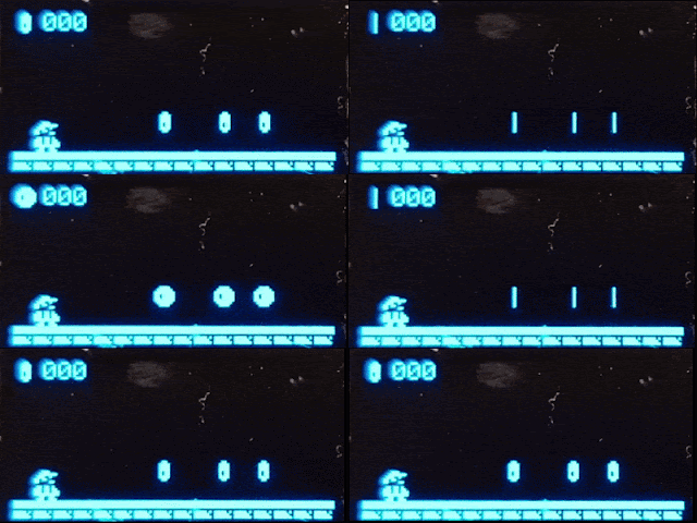
This is part 2 of my ATtiny Mario project - part one is here  -  a Mario-type game I made for the ATtiny85 AVR as a fun way of learning about the chip.  After writing the software, I decided I wanted a nice housing for the mass of wires on my breadboards and thought it would cool to put it into a NES-style controller, which is what this post will discuss.

ATtiny Mario

Image
ATtiny85 Mario Challenge! The ATtiny85 microcontroller is a capable but compact AVR.  However with only 8K of program memory, 512 bytes of EEPROM, 512 of SRAM and only 8 pins (3 of which are dedicated to the usual suspects of Vcc, GND and RESET), it best suited to performing tasks where memory demands are not large, and only a few pins are required for interfacing.  

Arduino and Raspberry Pi serial communciation

Image
Want to hook up your Arduino to your Raspberry Pi and send data between the two?  Read on! So you have your Arduino robot, or weather station and you want to send data back and forth with a Raspberry Pi?  The hardware hookup is really easy, but we have to configure a few things on the Pi. Hardware connections We'll use the serial UART pins on the Raspberry Pi Zero GPIO for this example, and transfer data from an Arduino to a Raspberry Pi zero, though all Raspberry Pis and Arduinos are capable of this feat.  The UART is a common serial communication protocol comprised of two pins labelled, RX (receive data pin) and "TX" (transmit data pin).  Wiring is easy - hook up the desired RX pin on the Arduino to the Raspberry Pi TX pin, and the Arduino TX to the Raspberry Pi RX pin.  As always, make sure you connect the ground line  between the Arduino and the Raspberry Pi.  If the particular Arduino model you are using is powered by 5V (find out by measurin...

PS2 controller as a radio controller!

Image
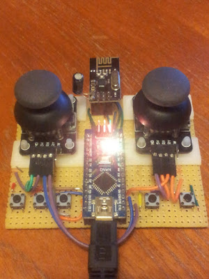
Turning a PS2 controller into a wireless radio controller with Arduino Mini and an nRF24l01 radio module I have previously described a project to transmit PS2 controller signals by radio .  The project featured an Arduino Nano that read the PS2 signals and transmitted them with an nRF24l01 module.  Recently I have been inspired to incorporate the battery, charging circuit and Arduino right into the controller - heavily inspired by this project here:

Getting started with the Pro Micro Arduino Board

Image
This is a brief guide to getting started with the Pro Micro Arduino Board (Atmega32U4) - not to be confused with the Pro Mini (which utilises the Atmega328P)!  Note that the Pro Micro board comes in two flavours/flavors - 5V @ 16 MHz and 3.3V @ 8 MHz, so make sure you know which you have before getting started.  It should be indicated on the bottom silkscreen of the bottom, or you could take a voltmeter and measure VCC against GND - it will be either 5V or 3.3V.

Adding LCD character display to Attiny85 project

Image
LCD character displays are a pretty useful addition to a project for providing a simple test output.  However if we use them in 4-bit or 8-bit parallel-mode they can be pretty greedy on pins, not to mention the software overhead with custom libraries.  I've been programming Attiny85 chips recently, where pins are certainly very much at a premium.  I wanted to add an 4-line LCD character output to the project, and luckily there are version of LCD displays that use serial inputs (I2C/UART/SPI) to control the input, meaning that if we use UART we only have to use a single pin to control output - excellent!

Sending IR remote control signals

Image
In my previous post , we looked at how to grab an 38 kHz modulated IR signal, analyse and process it. Now we'll look at a couple of different ways to transmit a modulated IR signal - first with an Arduino Nano, and then with an ESP-01S board. UPDATE: I have now used I2S to accurately transmit a modulated IR signal with the ESP8266 chip

Decoding 38 kHz IR signals with an Arduino Nano

Image
So... I have ambitions to use an ESP8266 board to control an IR LED and switch things on and off according to Alex voice control.  I have discussed how to implement Alexa voice control on an ESP-01S board here .  In this blog post I'll discuss how to grab, analyse and process an IR signal, ready to be re-transmitted.  In this case, I am using an TSOP4838 IR receiver, which takes an IR signal modulated at 38 kHz and demodulates to the corresponding 1s and 0s.  What is signal demodulation? This explains signal modulation excellently (stolen from SB-projects ):

Controlling my quadcopter with a PS2 controller

Image
I can now control my quadcopter with a PS2 controller - really cool!  The magic control box is powered either from the Arduino Nano inside and communicates with the quadcopter via radio, or a lipo battery, which is rechargeable over USB.  LEDs on the top feedback about the drone status and look really awesome. UPDATE: I have now incorporated the control electronics, and a long distance radio module directly into the PS2 controller!

Height and vertical velocity Kalman filtering on MS5611 barometer

Image
Height and vertical velocity from a MS5611 barometer Steps towards vertical flight control This isn't a post explaining how Kalman filters work, I assume some working knowledge.  Instead I wanted to record the process of developing a Kalman filter to derive both the height and the vertical velocity of a quadcopter using a MS5611 barometer, as it may be useful to others.  After recording some flight data on my quadcopter EEPROM, I then spat the output to a PC for post-processing and model training.  In Python I used a Kalman class to generate the following Kalman filter ( Wikipedia: Kalman filter ) based on the barometric height data.

The Fast and the Furious World (of Trigonometric Functions on ATMega328)

Image
Atan2 algorithms - speed vs accuracy Running trigonometric functions on an 8-bit AVR is inevitably going to be slow.  Floating point operations come with speed overheads and the most accurate algorithms usually come at a further timing price.  The arctangent function (atan/atan2) is ubiquitously useful, and especially so for Quadcopter's and robotics.  Briefly, an  atan2   function takes Y and X as arguments and works out which quadrant the tangent angle is in, and uses that to call a corresponding  atan   function.  I have been investigated the timings of various trigonometric functions on an ATMega328p chip running at 16 MHz, and in particular exploring 4 atan2 implementations and their trade-offs for accuracy.

A tale of two UART devices

Image
Resolving UART bus conflicts and voltage levels I wanted to record two potential issues I found with using my custom Atmega328p board with onboard USB FT232 when an HC-05 bluetooth module in introduced, in the hope it may well be helpful to others. Above:   A small piece of perfboard modifies the Bluetooth socket to include a 5V to 3.3V voltage divider on the Bluetooth HC-05 RX line (10 and 20kohm resistors).  The red wire provides a direct line from the Bluetooth HC-05 TX output and the Atmega328p RX input, thereby granting it preference when the HC-05 module is present.  It's not quite clear from the picture, but the RX input pin is bent up out of the socket and a 1k resistor connects the FT232 TX output (see below).

Customising Optiboot

Image
I wanted to setup programming my custom Atmega328p board over Bluetooth.  Some have used the connection pin to control the Reset pin of the AVR.  However I want to use Bluetooth constantly, and only trigger a reset upon receiving a specific string sequence.  This requires tweaking the bootloader, using Optiboot as a basis: (1) Change Baudrate to be mutually compatible with Bluebooth and AVR. (2) Set an EEPROM byte in the main application, which could be read (and written) in the Optiboot routine. Setting up Optiboot in the Atmel environment: - Setup a project as usual in Atmel Studio - Copy files over from github to the project folder: optiboot.c, pindefs.h, stk500.h and boot.h. EDIT: It seems there is an AtmelStudio folder already set up on github . Setting baud rate to be compatible with AVR and Bluetooth module: 57600 bps - Insert #define BAUD_RATE 57600 (as required) into optiboot.c . - Compile and link project with following settings: Compiler Mis...

Radio control

Image
Accessing  quadcopter memory over radio The usual method of controlling quadcopters is to transmit a train of PPM signals from a radio transmitter, measure the length of the individual pulses on a microcontroller, via a radio receiver .  As part of my DIY ethos, and as a learning exercise, I have made the above controller with an nrf24l01 moduled and an Arduino Nano.  In a nutshell, the Arduino Nano captures the 2D joystick positions, used for yaw, throttle, pitch and roll, and the button presses.  A data packet is then sent by radio to the Quadcopter.  In fact there is a more powerful implementation going on.  What is interesting is how the controller sends data to the Quadcopter - it actually manipulates the memory directly on the Quadcopter AVR - how does it do that? Well, first of all the Quadcopter defines the memory addresses that the controller has access to by setting recording a pointer to the desired variable - note that the cast means...

Stuck in Atmega328 reset loop?

Image
Kill switch killing... but stuck in reset loop I wanted to add a kill switch to my quadcopter project so that in the case of crash/emergency, a button might be pushed on the radio controller, the quadcopter motors stopped and the flight controller chip is reset.  A good way of resetting an AVR is to invoke the watchdog timer and put the chip into an infinite loop - the watchdog times out and the chip is reset.  This is fairly straightforward when the kill/reset signal is received: #include <avr/wdt.h> void kill_drone(void) { USART_Pputstring(PSTR("Kill drone!\n")); wdt_reset(); wdt_enable(WDTO_15MS); while(1){}; } where the two watchdog handling functions are defined in avr/wdt.h. The AVR is reset, but keeps on reseting, initialising and resetting in an infinite loop... Watchdog Groundhog day! It turns out that the watchdog register settings are enabled, even after a reset !  To get around this, the watchdog must be turned off at the ea...

A few teething problems

Image
A couple of teething problems in my board design. Lessons learnt and problems solved! Design philosophy Because you get 3 boards from OSHPark, and really I only needed one for this project, I wanted to 'future-proof' my board so that I could use the other two effectively as an Aruduino-type board for other future projects.  Therefore I have broken out every pin that I can and added convenient sockets for the following peripherals, which are likely to be useful in future projects (as well as in this one): - Bluetooth module (HR-04) - nRF240l radio - GY-86 10-DOF module (MPU6050 + MC5883l + MS5611) - Onboard EEPROM 4Mbits/500kbytes (a25l040-f AMIC) - ISP: Programming chip and flashing with bootloader for Arduino GUI use. - FT232RL for convenient serial USB communication. It's always a bit of a pain to wire up the nRF2401 radios and with this board design I can very easily drop on into the correct socket, and also add a bluetooth module and not having to worry...

PCBs have arrived!

Image
Totally board A flurry of excitement this morning... The PCBs arrived from OSH Park!  I have to say they look gorgeous! I am in no way biased. As a quick sanity check of the custom USB part, I dropped in a USB socket and it fitted like a dream.  I can't wait to break out the soldering iron! Fingers crossed there aren't any absolute clangers in the board design!

DMP 6-axis processing

Image
Rock, Roll and Yaw... and Barometric pressure! A change to the Quadcopter design!  Previously I had MPU6050 on a GY-521 board (acc+gyro) and the magnetometer HMC5883L on a GY-271.  I decided I wanted to have a barometer on the flight board for height control.  A bit of research revealed the MS5611 was a pretty sensitive standard barometer.  There wasn't room to add a separate barometer module to the flight control board and in fact it was cheaper to replace the GY-521 and GY-271 board with a single board, GY-86, that contained the accelerometer, gyroscope, magnetometer and barometer!  On this single board we have the MPU6050 accelerometer and gyroscope, magnetometer HMC5883L and barometer MS5611. Calculating quadcopter orientation So I'm using the GY-86 10 DOF board to calculate the orientation of the quadcopter.  We have the MPU6050 processing chip on board, and although we can read off the various sensors readings, a technology/software ...

Clone wars

Image
Cloning Arduino core ... using TIMER0 in Arduino Sometimes you want to use TIMER0 in the Arduino IDE but default inclusion of Arduino libraries means that you can't have control over TIMER0 (it is used by millis() and delay() functions).  In a recent project, I wanted to use all the Atmega328 timers, and for various reasons, still use the Arduino IDE. The solution is simple .  Rather than hacking the core library, we'll clone the Arduino core library, define a board that uses the core library and then hack it to our specifications.  Steps: (1)  Clone the Arduino core Copy the Arduino core (C:\Program Files (x86)\Arduino\hardware\arduino\avr\cores) as "arduinohacked" -  the new core directory mustn't have an underscore in it! (2) Define a new board to use the cloned core library Open "C:\Program Files (x86)\Arduino\hardware\arduino\avr\boards.txt" and put the following text at the bottom.  This will define a new board in the Arduino IDE.  I...