Sending IR remote control signals
In my previous post, we looked at how to grab an 38 kHz modulated IR signal, analyse and process it.
Now we'll look at a couple of different ways to transmit a modulated IR signal - first with an Arduino Nano, and then with an ESP-01S board.
UPDATE: I have now used I2S to accurately transmit a modulated IR signal with the ESP8266 chip
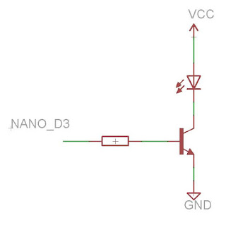 It looks weird to me that there isn't a current limiting resistor in series with the LED, but I got this schematic from the Adafruit website, which I tend to trust... Vcc is 5V and the resistor value is 470 Ohm. Also the IR LED is only switched on for fractions of a second, which will help any issue of current overload.
Okay! So now we need a function "send_IRcode" that decodes the HEX signal, converts to 1s and 0s, then generates the timings necessary to send out the IR signal - then set it up to send out - phew! Here is such a function:


So first the send functions works out for each timing how many multiples of 5 pulses are used, and what the remainder (if any) is needed. For example, if we needed to send 23 pulses, that would be 4 lots of 85 to send (4 x 5 = 20 pulses), followed by the number "21" (3 pulses). Once we have these calculated, and it is trivial to do so, we can step through the hex signal sequence and use some macros to send the bytes.
Guess what? This actually works! Now I can control stuff with an IR remote, using an ESP8266 board. Now to hook this up to Alexa and control stuff with my voice (see my previous post)! Finally, a confession - this is not 100% reliable. In fact, I have to send the code approx. 3 times to be sure it will send, but for the ease of implementation, this is an okay trade-off. This will be a problem if we need to accurately repeat a signal in quick succession, but for now, I'm fairly happy with this.
EDIT: At first I mixed up the order of LSB and MSB in the UART protocol - this still worked! That meant I was sending "170" instead of "85" and the remainder array was: {128,160,168,170}. I wonder how important the remainder actually is? I wonder if I can improve the send success rate by just sending 170s or 85s and perhaps modifying how many bytes are sent if necessary?
UPDATE: I have now used I2S to accurately transmit a modulated IR signal with the ESP8266 chip
Now we'll look at a couple of different ways to transmit a modulated IR signal - first with an Arduino Nano, and then with an ESP-01S board.
UPDATE: I have now used I2S to accurately transmit a modulated IR signal with the ESP8266 chip
Arduino Nano: Transmitting 38 kHz IR signals
Okay, so using the Arduino Nano to transmit the 38 kHz modulated IR signal is pretty straightforward. First of all, some setup:
#define TIME_BASE (1000000/38000.0f) // In microseconds

#define LOW_TIME 24
#define HIGH_TIME_0 19
#define HIGH_TIME_1 62

struct myIRstruct{
  float timebase=TIME_BASE;
  uint8_t lt=LOW_TIME, ht0=HIGH_TIME_0, ht1=HIGH_TIME_1; // Low time
  uint16_t low, high; // Leading sequence
  uint8_t IRcode[8]= {0,0,0,0,0,0,0,0};
  uint8_t len = 0;
};
This means we can define our previously collected IR signal as:
struct myIRstruct mycode;

// 0x32CD817E
// 345, 169
// 32 bits
mycode.len=32;
mycode.low = 345; // This is 9 ms
mycode.high = 169; // This is 4.5 ms
mycode.IRcode[0]=0x32;
mycode.IRcode[1]=0xCD;
mycode.IRcode[2]=0x81;
mycode.IRcode[3]=0x7E;
and we can then call a function, passing on this defined signal as the parameter:
send_IRcode(&mycode);In terms of hardware, I hooked up my IR LED like so:
Okay! So now we need a function "send_IRcode" that decodes the HEX signal, converts to 1s and 0s, then generates the timings necessary to send out the IR signal - then set it up to send out - phew! Here is such a function:
void send_IRcode(struct myIRstruct *ircode)
{
   uint8_t byte_index, bit_index;
   uint16_t s=0;
   byte_index = ircode->len/8;
   bit_index = ircode->len - (8*byte_index);

   // Decode:

    timeseq[0] = ircode->low;// leader sequence
    timeseq[1] = ircode->high;
    s=2;

     for (uint8_t b=0;b<=byte_index;b++)
      for (uint8_t bt=0;bt<8;bt++)
      {
        if (b<byte_index || (b==byte_index && bt<bit_index))
        {
          uint8_t v = ircode->IRcode[b]&(1<<bt);
          timeseq[s] = ircode->lt;
          s++;
          if (v) timeseq[s] = ircode->ht1;
          else timeseq[s] = ircode->ht0;
          s++;
        }
     }

     timeseq[s] = ircode->lt; // End bit
     s++;

    for (uint16_t i=0; i<s;i++)
      Serial.println(timeseq[i]);

    sequence_index = 0;
    sequence_len = s;
    Serial.print("Sequence_len:"); Serial.println(sequence_len);
    pulse = 0;
    IR_WAIT = timeseq[0];

    //Pin 3 is high
    TCCR2A |= _BV(COM2B1); // enable output pin 3
    TCNT2 = 0; // reset timer
    TIMSK2 |= (1 << OCIE2B); //enable interrupt
}
Firstly, the length of the bit sequence is decoded from the hex code provided, and this is used to generate and an array "timeseq", populated with timings of high and low. The timeseq array is printed out for examination, and some code to kick off an interrupt is invoked. Let's back up a second - what is this about an interrupt? So I'm using Timer2 to generate a 38 kHz (actually 38.4 kHz PWM signal, with 50% duty). I'm then asking TIMER2 to trigger an interrupt when a cycle is finished. In this way we can then count up the number of 38 kHz cycles at toggle the output (on or off) depending on whether we need to output a modulated HIGH or a LOW. The PWM timer is linked to Pin 3 (D3).
void setIrModOutput() // sets pin 3 going at the IR modulation rate
{

  pinMode(3, OUTPUT);
  TCCR2A = _BV(WGM21) | _BV(WGM20); //enable pin3, fast pwm mode with OCRA top.
  TCCR2B = _BV(WGM22) | _BV(CS21); // Sys / 8
  OCR2A = 51; // freq = 16 MHz / 16 / (51+1) = 38.4 kHz
  OCR2B = 26; // duty cycle (50%)
  sei();
}
This function "setIrModOutput" should be called from setup(). Finally we need the code in the interrupt that handles changing the modulated output:
#define clr_bit(reg,bit) reg &= ~(1<<bit)

ISR(TIMER2_COMPB_vect){  // Interrupt service routine to pulse the modulated pin 3
    pulse++;

  if(pulse >= IR_WAIT) { // change number for number of modulation cycles in a pulse
    pulse = 0;
    TCCR2A ^= _BV(COM2B1); // toggle pin 3 enable, turning the pin on and off
    sequence_index++;
    if (sequence_index>=sequence_len)
    {
      clr_bit(TIMSK2, OCIE2B); // end of sequence, disable interupt
      clr_bit(TCCR2A, COM2B1); //switch off IR LED
    }
    else
    {
       IR_WAIT = timeseq[sequence_index];
    }
  }
}
That's the final part of the puzzle here - once the IR signal has finished sending, the pin is turned off - and it works! I can now control devices using IR and an Arduino Nano.ESP-01S: Transmitting 38 kHz IR signals
So how can we use the ESP-01S to transmit IR signals? Can we use a similar method? Probably. I tried playing around with bit-banging a 38 kHz signal, but it didn't work and I had problems using the microsecond delay function... I think there are also issues with interrupts from the onboard WiFi side of things messing things up. In any case, I read a passing reference to a "dirty hack" of using a UART signal at the correct baud to send a modulated IR signal. I liked the idea, and it turned out to be fairly simple to implement. It turns out, further to the default UART RX/TX broken out on the ESP-01S board, there is a second hardware UART that uses GPIO2 as the alternative TX. We can send characters to this serial port (Serial1) and by choosing them carefully to have alternating 0s and 1s, we can transmit a pseudo-modulated signal using hardware!
First of all, the circuit:
In this case, Vcc is 3.3V. The resistors feeding the NPN transistors are 470 Ohm, and the pullup resistors are 1 kOhm. These values are pretty unoptimised and could no doubt be improved. The first transistor stage acts as a logic NOT gate to invert the UART signal. The UART signal is HIGH when no data is being transmitted, so needs to be inverted, otherwise the IR LED would be constantly switched on. The second transistor acts simply as a digital switch. The first-stage pullup resistor is important - if GPIO2 is not HIGH when the ESP8266 chip boots up, a certain state of the chip is entered and user code is not executed. Therefore if we connect GPIO2, we need this pullup resistor to keep the bootup checks happy.
First we setup the alternative serial port:
pinMode(2, INPUT_PULLUP);
Serial1.begin(76800, SERIAL_8N1);
Serial1.flush();
Using the same code as for the Arduino Nano to define the IR signal:
#define TIME_BASE (1000000/38000.0f) // Microseconds

#define LOW_TIME 24
#define HIGH_TIME_0 19
#define HIGH_TIME_1 62

struct myIRstruct{
  float timebase=TIME_BASE;
  uint8_t lt=LOW_TIME, ht0=HIGH_TIME_0, ht1=HIGH_TIME_1;
  uint16_t low, high; // Leading sequence
  uint8_t IRcode[8]= {0,0,0,0,0,0,0,0};
  uint8_t len = 0;
};

.
.
.

struct myIRstruct mycode;

mycode.len=32;
mycode.low = 345;
mycode.high = 169;
mycode.IRcode[0]=0x32;
mycode.IRcode[1]=0xCD;
mycode.IRcode[2]=0x81;
mycode.IRcode[3]=0x7E;
The send function is based on the idea that we can send characters with certain bit patterns to the hardware UART and it will produce a modulated signal at about 38 kHz (actually 38.4 kHz). For example if we send sequences of "85"s to the UART with the 8N1 serial mode, we can produce a pulse train of modulated signal, with 5 modulations per byte. Where we have to send a number of pulses that is not a 5 times multiple of the 38 kHz period length, we can send other bytes to send the remainder i.e. 3, or 2, or 1. This method isn't perfect as sending 4 lots of pulses is not uniquely possible and there will always be a STOP bit sent, but despite it's hacky nature, it works!
void send_IRcode(struct myIRstruct *ircode)
{
   uint8_t byte_index, bit_index;
   byte_index = ircode->len/8; // 32 = 4, 0 remainder
   bit_index = ircode->len - (8*byte_index);

    Serial.println("SEnding code..>");
    Serial.println(byte_index);
    Serial.println(bit_index);

   // Decode:

    const uint8_t remain[4] = {1,5,21,85}; // 1, 2,3,4 --> 0,1,2,3

    uint8_t whole_lead, remainder_lead,whole_lt, remainder_lt;
    uint8_t whole_ht0, whole_ht1,whole_lead_high;

    whole_lead = (uint8_t) (ircode->low/5.0f);
    remainder_lead = ircode->low - 5*whole_lead;

    whole_lt = (uint8_t) (ircode->lt/5.0f);
    remainder_lt = ircode->lt - 5*whole_lt;

    whole_ht0 = (uint8_t) (ircode->ht0/5.0f);
    whole_ht1 = (uint8_t) (ircode->ht1/5.0f);
    whole_lead_high = (uint8_t) (ircode->high/5.0f);

    // Code sequence:
    // Leader sequence

    SEND_Nbytes(whole_lead,85);

    if (remainder_lead>0) SEND_remainder(remainder_lead);
    SEND_Nbytes(whole_lead_high,0);

     for (uint8_t b=0;b<=byte_index;b++)
     {
      for (uint8_t bt=0;bt<8;bt++)
      {
        if (b<byte_index || (b==byte_index && bt<bit_index))
        {
          uint8_t v = ircode->IRcode[b]&(1<<bt);

          SEND_Nbytes(whole_lt, 85)
          if (remainder_lt>0) SEND_remainder(remainder_lt)

          if (v) SEND_Nbytes(whole_ht1, 0)
          else SEND_Nbytes(whole_ht0, 0)
        }
     }
    }

  SEND_Nbytes(whole_lt,85)
  Serial.println("sent");

}
Where the macros are defined as:
#define SEND_Nbytes(n,b) {for ( uint8_t  j=0; j<n; j++) Serial1.print((char)b);}
#define SEND_remainder(r) Serial1.print((char)remain[r-1]);
Guess what? This actually works! Now I can control stuff with an IR remote, using an ESP8266 board. Now to hook this up to Alexa and control stuff with my voice (see my previous post)! Finally, a confession - this is not 100% reliable. In fact, I have to send the code approx. 3 times to be sure it will send, but for the ease of implementation, this is an okay trade-off. This will be a problem if we need to accurately repeat a signal in quick succession, but for now, I'm fairly happy with this.
EDIT: At first I mixed up the order of LSB and MSB in the UART protocol - this still worked! That meant I was sending "170" instead of "85" and the remainder array was: {128,160,168,170}. I wonder how important the remainder actually is? I wonder if I can improve the send success rate by just sending 170s or 85s and perhaps modifying how many bytes are sent if necessary?
UPDATE: I have now used I2S to accurately transmit a modulated IR signal with the ESP8266 chip


Comments
Post a Comment