Posts

Showing posts with the label quadcopter

PS2 controller as a radio controller!

Image
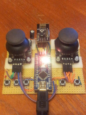
Turning a PS2 controller into a wireless radio controller with Arduino Mini and an nRF24l01 radio module I have previously described a project to transmit PS2 controller signals by radio .  The project featured an Arduino Nano that read the PS2 signals and transmitted them with an nRF24l01 module.  Recently I have been inspired to incorporate the battery, charging circuit and Arduino right into the controller - heavily inspired by this project here:

Controlling my quadcopter with a PS2 controller

Image
I can now control my quadcopter with a PS2 controller - really cool!  The magic control box is powered either from the Arduino Nano inside and communicates with the quadcopter via radio, or a lipo battery, which is rechargeable over USB.  LEDs on the top feedback about the drone status and look really awesome. UPDATE: I have now incorporated the control electronics, and a long distance radio module directly into the PS2 controller!

Height and vertical velocity Kalman filtering on MS5611 barometer: part 2

Image
Adding accelerometer data to the Kalman filter In my last post I wrote about a Kalman filter to take the MS5611 barometer data and derive both the quadcopter height, and the vertical velocity.  It worked reasonably well but there was a compromise between noise and latency of the filter.  To get even better results, I have incorporated now the accelerometer.  We could produce a new Kalman filter using the height, velocity and acceleration in the state vector, but it turns out we can simply amend our previous filter and include the acceleration in the control vector to improve the predicted state.

Height and vertical velocity Kalman filtering on MS5611 barometer

Image
Height and vertical velocity from a MS5611 barometer Steps towards vertical flight control This isn't a post explaining how Kalman filters work, I assume some working knowledge.  Instead I wanted to record the process of developing a Kalman filter to derive both the height and the vertical velocity of a quadcopter using a MS5611 barometer, as it may be useful to others.  After recording some flight data on my quadcopter EEPROM, I then spat the output to a PC for post-processing and model training.  In Python I used a Kalman class to generate the following Kalman filter ( Wikipedia: Kalman filter ) based on the barometric height data.

The Fast and the Furious World (of Trigonometric Functions on ATMega328)

Image
Atan2 algorithms - speed vs accuracy Running trigonometric functions on an 8-bit AVR is inevitably going to be slow.  Floating point operations come with speed overheads and the most accurate algorithms usually come at a further timing price.  The arctangent function (atan/atan2) is ubiquitously useful, and especially so for Quadcopter's and robotics.  Briefly, an  atan2   function takes Y and X as arguments and works out which quadrant the tangent angle is in, and uses that to call a corresponding  atan   function.  I have been investigated the timings of various trigonometric functions on an ATMega328p chip running at 16 MHz, and in particular exploring 4 atan2 implementations and their trade-offs for accuracy.

Quadcopter code structure

Image
I've been meaning to post this for a while but after soldering everything together and correcting the errors in the PCB (details blogged here: Resolving UART bus conflict and Power control ), THE THING FLIES !  In fact it flies pretty well. I thought I would record the code structure of the quadcopter. Below, psuedo-code for the quadcopter main loop, focusing on stabilisation:

A tale of two UART devices

Image
Resolving UART bus conflicts and voltage levels I wanted to record two potential issues I found with using my custom Atmega328p board with onboard USB FT232 when an HC-05 bluetooth module in introduced, in the hope it may well be helpful to others. Above:   A small piece of perfboard modifies the Bluetooth socket to include a 5V to 3.3V voltage divider on the Bluetooth HC-05 RX line (10 and 20kohm resistors).  The red wire provides a direct line from the Bluetooth HC-05 TX output and the Atmega328p RX input, thereby granting it preference when the HC-05 module is present.  It's not quite clear from the picture, but the RX input pin is bent up out of the socket and a 1k resistor connects the FT232 TX output (see below).

Customising Optiboot

Image
I wanted to setup programming my custom Atmega328p board over Bluetooth.  Some have used the connection pin to control the Reset pin of the AVR.  However I want to use Bluetooth constantly, and only trigger a reset upon receiving a specific string sequence.  This requires tweaking the bootloader, using Optiboot as a basis: (1) Change Baudrate to be mutually compatible with Bluebooth and AVR. (2) Set an EEPROM byte in the main application, which could be read (and written) in the Optiboot routine. Setting up Optiboot in the Atmel environment: - Setup a project as usual in Atmel Studio - Copy files over from github to the project folder: optiboot.c, pindefs.h, stk500.h and boot.h. EDIT: It seems there is an AtmelStudio folder already set up on github . Setting baud rate to be compatible with AVR and Bluetooth module: 57600 bps - Insert #define BAUD_RATE 57600 (as required) into optiboot.c . - Compile and link project with following settings: Compiler Mis...

Radio control

Image
Accessing  quadcopter memory over radio The usual method of controlling quadcopters is to transmit a train of PPM signals from a radio transmitter, measure the length of the individual pulses on a microcontroller, via a radio receiver .  As part of my DIY ethos, and as a learning exercise, I have made the above controller with an nrf24l01 moduled and an Arduino Nano.  In a nutshell, the Arduino Nano captures the 2D joystick positions, used for yaw, throttle, pitch and roll, and the button presses.  A data packet is then sent by radio to the Quadcopter.  In fact there is a more powerful implementation going on.  What is interesting is how the controller sends data to the Quadcopter - it actually manipulates the memory directly on the Quadcopter AVR - how does it do that? Well, first of all the Quadcopter defines the memory addresses that the controller has access to by setting recording a pointer to the desired variable - note that the cast means...

Stuck in Atmega328 reset loop?

Image
Kill switch killing... but stuck in reset loop I wanted to add a kill switch to my quadcopter project so that in the case of crash/emergency, a button might be pushed on the radio controller, the quadcopter motors stopped and the flight controller chip is reset.  A good way of resetting an AVR is to invoke the watchdog timer and put the chip into an infinite loop - the watchdog times out and the chip is reset.  This is fairly straightforward when the kill/reset signal is received: #include <avr/wdt.h> void kill_drone(void) { USART_Pputstring(PSTR("Kill drone!\n")); wdt_reset(); wdt_enable(WDTO_15MS); while(1){}; } where the two watchdog handling functions are defined in avr/wdt.h. The AVR is reset, but keeps on reseting, initialising and resetting in an infinite loop... Watchdog Groundhog day! It turns out that the watchdog register settings are enabled, even after a reset !  To get around this, the watchdog must be turned off at the ea...

A few teething problems

Image
A couple of teething problems in my board design. Lessons learnt and problems solved! Design philosophy Because you get 3 boards from OSHPark, and really I only needed one for this project, I wanted to 'future-proof' my board so that I could use the other two effectively as an Aruduino-type board for other future projects.  Therefore I have broken out every pin that I can and added convenient sockets for the following peripherals, which are likely to be useful in future projects (as well as in this one): - Bluetooth module (HR-04) - nRF240l radio - GY-86 10-DOF module (MPU6050 + MC5883l + MS5611) - Onboard EEPROM 4Mbits/500kbytes (a25l040-f AMIC) - ISP: Programming chip and flashing with bootloader for Arduino GUI use. - FT232RL for convenient serial USB communication. It's always a bit of a pain to wire up the nRF2401 radios and with this board design I can very easily drop on into the correct socket, and also add a bluetooth module and not having to worry...

PCBs have arrived!

Image
Totally board A flurry of excitement this morning... The PCBs arrived from OSH Park!  I have to say they look gorgeous! I am in no way biased. As a quick sanity check of the custom USB part, I dropped in a USB socket and it fitted like a dream.  I can't wait to break out the soldering iron! Fingers crossed there aren't any absolute clangers in the board design!

DMP 6-axis processing

Image
Rock, Roll and Yaw... and Barometric pressure! A change to the Quadcopter design!  Previously I had MPU6050 on a GY-521 board (acc+gyro) and the magnetometer HMC5883L on a GY-271.  I decided I wanted to have a barometer on the flight board for height control.  A bit of research revealed the MS5611 was a pretty sensitive standard barometer.  There wasn't room to add a separate barometer module to the flight control board and in fact it was cheaper to replace the GY-521 and GY-271 board with a single board, GY-86, that contained the accelerometer, gyroscope, magnetometer and barometer!  On this single board we have the MPU6050 accelerometer and gyroscope, magnetometer HMC5883L and barometer MS5611. Calculating quadcopter orientation So I'm using the GY-86 10 DOF board to calculate the orientation of the quadcopter.  We have the MPU6050 processing chip on board, and although we can read off the various sensors readings, a technology/software ...

Flashing SimonK Hex to ESCs

Image
After some experiments applying PWM signals to an ESC controller for the Quadcopter, it rapidly became clear that the response was sluggish.  The "SimonK hex" firmware for ESC controllers appears to be the community's standard for rapidly responding ESCs.  I'm using the "MultiStar LBEC 2A 15A" ESCs from Turnigy.  After slipping off the ESC's cover slip with a razor the chip to flash becomes apparent - Atmel ATMega8A. This video on Youtube was very useful: Firstly the correct hex has to be chosen for these specific ESCs from a firmware archive .  These ESC appear to be discontinued on HobbyKing so I had to chose something that appeared very closely related - "kda.hex". The flashing software, KKMulticopter tool , is a convenient way of doing things (though avrdude from the command line manually is of course possible).  From the KKMulticopter tool, choose (1) Programmer = USBtiny simple USB programmer (or whatever yours is) (2) Port...

4 x 16 bit servo control on Atmega328p

Image
Controlling four motors with Atmega328 Timer1 One of the challenges in a quadcopter project is to correctly control the four thrust motors, via ESCs.  The control is effected by a pulse between 1-2 ms.  In ESC controllers, the refresh rate can be as low as 8 Hz or 20 Hz.  In quadcopters this refresh rate is far too slow - I have seen 100-200 Hz suggested as a suitable update frequency.  The "SimonK" hex is often reflashed to ESC controllers, as it has a refresh rate of approximately 488 Hz, very close to the theoretical refresh limit of just below 500 Hz. Algorithm idea Using the Atmega328 chip, we have only one 16-bit timer available, Timer 1.  Of course there are two other timers, but they are 8 bit timers, and I really want to stick to the resolution of the 16-bit timers.  We could consider using an AVR with four 16-bit hardware timers and use the four timer output pins, but it is interesting to see what can be done with just one.  So we ...

HC-05 troubleshooting

Image
Some HC-05 modules are more equal than others I've been playing with some cheap HC-05 bluetooth modules I picked up off Amazon.  They are a very convenient and easy way to add remote control to a project, using two wire UART (RX/TX) in the usual way, so can replace an existing serial connection to a PC for example.  They work pretty much out the box and there are loads of guides to using them.  I thought I would share a few thoughts on using these modules though as I've come to realise that all HC-05s are not created equal... There are some visual clues.  On the back of my modules I have an "EN" pin whereas some other HC-05 modules have a "KEY" pin.  The KEY pin is used to place the module into "AT command mode", by putting it high (3.3V) before powering up the module.  I initially thought that the EN pin was analogous to the KEY pin (a different name perhaps), but the EN pin can be used to disable the bluetooth module , which I guess is...

Quadcopter control board - part 1

Image
Quadcopters and custom Eagle parts So I finally started my quadcopter project!  I want it to do certain things - for simplicity, I wanted to use cheap modules that you can find on Ebay or Amazon for the accelerometer, gyroscope and magnetometer.  I decided to add a micro USB port as a convenient 5 V power source, but quickly reasoned that full USB support with a FT232RL chip would be an easy way interact with the board and to spit out debug information.  So I picked up a bunch of micro USB with through-hole female ports from Ebay for next to nothing... then promptly realised they were completely non-standard and I would have to create my own custom Eagle part .  This turned out to be really quite simple.  With digital vernier calipers in hand the footprint part I created (inset) in a prototype design turned out to be near perfect - result! For the accelerometer and gyroscope I'm using a MPU-6050, and for the magnetometer, a HMC5883L module.  Esse...