4 x 16 bit servo control on Atmega328p
Controlling four motors with Atmega328 Timer1
One of the challenges in a quadcopter project is to correctly control the four thrust motors, via ESCs. The control is effected by a pulse between 1-2 ms. In ESC controllers, the refresh rate can be as low as 8 Hz or 20 Hz. In quadcopters this refresh rate is far too slow - I have seen 100-200 Hz suggested as a suitable update frequency. The "SimonK" hex is often reflashed to ESC controllers, as it has a refresh rate of approximately 488 Hz, very close to the theoretical refresh limit of just below 500 Hz.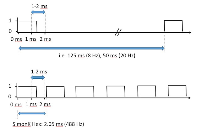
Algorithm idea
Using the Atmega328 chip, we have only one 16-bit timer available, Timer 1. Of course there are two other timers, but they are 8 bit timers, and I really want to stick to the resolution of the 16-bit timers. We could consider using an AVR with four 16-bit hardware timers and use the four timer output pins, but it is interesting to see what can be done with just one. So we are having to do the job of dedicated hardware, in software. In fact we have two compare thresholds with Timer 1, OCR1A and OCR1B, which means two interrupts can be triggered, effectively providing two 16-bit psuedo-timers (caveats, later). So we could set all four pins high at t=0, set OCR1A to the pin 1 trigger level and OCR1B to the pin 2 trigger level. When the interrupts fire, set the necessary pin low and set OCR1A/B to the difference remaining for the next pin, pin 2 or 4. Repeat the process on timer overflow. The principle advantage of this would be that refresh frequency can match the SimonK 488 Hz rate. The algorithm is outlined more clearly below.
Implementation
A little bit of Timer 1 control code setup:TCCR1A = 0; // No output on OC1A or OC1B, disable hardware PWM
TCCR1B = CLOCKBITS; // System clock, CK
// Set initial timer value:
TCNT1 = 0; //0;
TIMSK1 = (1<<OCIE1B) | (1<<OCIE1A) | (1<<TOIE1);
An example of the interrupt code for the OCRA compare:
ISR (TIMER1_COMPA_vect)
{
pin_low(DDRD,PWMouts[OCR1A_key].pin);
OCR1A_key = pwm_keys[2];
OCR1A = PWMouts[OCR1A_key].pwm;
}
I don't have an oscilloscope, so I then hooked up 4 LEDs to 4 outputs and implemented the algorithm with the TIMER1_COMPA_vect, TIMER1_COMPB_vect and TIMER1_OVF_vect. I set the clock scaling in TCCR1B to 0b101 (1024 pre-scaling) rather than 1. That means 16000 clock ticks at 16 MHz corresponds to 1.024 seconds, rather than 1.0 ms, to slow it down to check the sequence triggering visually.
The algorithm relies on the array being sorted as events need to trigger in sequence. This is interesting in and of itself, as I use five "SWAP" macros generated by a Bose-Nelson algorithm which gives an efficient (the most?) way of sorting a list of four objects. In fact I am sorting on a list to generate a sorted list of indexes to that list (if that makes any sense to you), but that is a minor detail.
When TCCR1B = 1, no clock scaling, setting OCR1A/B values between 16000-32000, a pulse of 1-2 ms is generated.
The problem(s)
This works, but there is a problem. When the 4 different timing values get close enough to each other, one or two of LEDs fails to switch off. I only allowed one timer cycle, and set the pre-scaler to 1 - therefore too fast to monitor by eye, but if a pin remains on, then something has gone wrong. By experimentation, I found that if I set all the pulse lengths to the same value (worse case), pin 3 and pin 4 fail to go low. In order to get the correct behaviour, the timing difference (deltaA or deltaB in the diagram) can be a minimum of about 200 clock cycles. So what's going on here? Well, there are two things:(1) The conditions for pin 3 interrupt to trigger are met, but occur during TIMER1_COMPA_vect (for pin 1) so the interrupt flag is never set.
(2) Interrupts for pin 3 might occur during TIMER1_COMPB_vect and the interrupt flag is set correctly, but must wait for the current running interrupt to stop blocking.
If I calculate how long each interrupt takes to execute (see blog post on disassembling hex) it turns out to be around 100 clock cycles. As TIMER1_COMPA_vect (pin 1) and TIMER1_COMPA_vect (pin 2) both block, pin 3 has to wait for 2 x 100 clock cycles before it can run. Is this a deal breaker? Well 200 clock cycles at 16 MHz corresponds to 12.5 us. That's 2.5% of the 500 us range. Even then that's the MAXIMUM range, I expect the pulses for a quadcopter will not have such a large range and therefore 12.5 us could be as much as a 10% error. Given the sorting algorithm will switch the exact identity of Pin 1-4 on the fly, this could result in a glitchy, switching behaviour. Not good.
A solution?
Of course all four pins don't need to be synchronised, as they communicate with four different ESCs. Given the problem of blocking by interrupts, that arises from insisting on bringing all the pins high at once, it seems a better solution to control the pins sequentially. Below I have shown this, controlling pin 1 and 3 (for example) on Timer 1 (OCR1A). This will give rise to a variable frequency to the ESC, but I think that shouldn't matter. If both Pin 1 and 3 have a minimum of 1 ms, plus the interrupt duties totaling 200 clock cycles, they update the ESCs at a rate of 497 Hz. A delay can be introduced to reduce it to 480 Hz. Alternatively if they run at 2 ms each, a rate of 249 Hz is generated. In either case, the pulse should be handled correctly by the ESC and provide a good update rate. OCR1B could be used in parallel to control pins 2 and 4 in an analogous manner (not shown).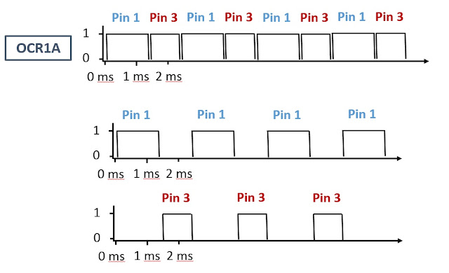
UPDATE: A simple parallel method was used ultimately to give the desired 250 Hz update rate.
References:
http://www.embedds.com/programming-16-bit-timer-on-atmega328/
http://maxembedded.com/2011/06/avr-timers-timer1/
http://www.avrfreaks.net/forum/tut-c-newbies-guide-avr-pwm-incomplete?name=PNphpBB2&file=viewtopic&t=68302


Comments
Post a Comment