8-Bit Computer: UART Transceiver for breadboard computer
You art UART
I have an increasing fascination with building 8-bit computers from TTL chips, sparked by the excellent Ben Eater series on YouTube, and deepened by a variety of examples on Hackaday. In the process of designing/building my own 8-bit computer, I wondered how easy it would be to implement a UART transceiver purely out of basic 7400 series ICs...

The finished design: UART Transceiver built from 7400 series ICs.
First things first, what actually is UART? UART or Universal Asynchronous Receiver Transmitter is a straightforward protocol allowing for 8-bits of data to be sent and received asynchronously, allowing a CPU/computer to communicate with the outside world. This is useful in itself, my 8-bit computer could talk back and forth to my laptop and use a serial monitor (i.e. Putty) as an interface to output and input text. However, more interestingly, I could program a boot-loader into my 8-bit computer, and then program the computer over the UART connection from my laptop! As Bluetooth modules such as HC-05 essentially interface with a CPU with UART, I could even use a Bluetooth module to program my 8-bit computer from afar! That would be, as they say, freakin' sweet. Some purists might consider the programming of the 8-bit computer by a much more powerful computer a bit of a cheat, but hey - it's my project and my rules! Feel free to program your home-built machine using DIP switches if you enjoy data entry more than programming and want that tedious authentic experience! The chip programming aside, I have at least restricted myself to simple TTL chips in the computer design - no Arduinos, Raspberry Pis, ESP8266s or other Turing complete modules will appear (after all, where would be the fun in that?).
UART protocol & design constraints
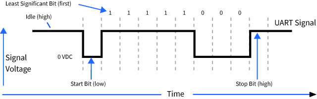
This is UART signal structure, borrowed from here. There is a start bit, indicated by an initial high to low transition, followed by the data byte (LSB first), and a high stop bit. Sometimes there is a parity bit, but it is optional and therefore I omitted it, for the sake of KISS - Keep It Simple Stupid. The timing of each bit is determined by the baud rate in bits per second (bps). i.e. a baud rate of 9600 bps means a bit is sent in 1/9600 = 104 microseconds. The waveform is fairly simple and this enables us to implement it entirely in hardware in logic chips.
I needed to select a crystal oscillator that would give me access to some standard baud rates for transmitting, preferably by diving by powers of two as this can be conveniently done with a binary counter. After some chin stroking, I decided to use a 2.4576 MHz crystal oscillator as this would let me send at 38400 bps (divide by 64), or 9600 bps (divide by 256).
UART Transmitter - TX
Parts list:
- 2.4576 MHz crystal oscillator
- 3 x 74LS161 4-bit counters
- 74LS674 16-bit shift register
- 74LS06 AND
- 74LS74 D-flip flop
- 74LS04 NOT
- Diode 1N4001
- 470 uF (!) capacitor (power supply smoothing)
Schematic
The UART transmitter is conceptually the simplest to understand. It is at its heart, merely a parallel-load serial-out shift register that loads in the data byte, observing the flanking start and stop bits, and clocks it out at the desired baud rate. The schematic below demonstrates this process. In (1) a 2.4576 MHz crystal oscillator is clocked down to 38,400 Hz using two 74LS161 4-bit counters, and then in (2) a 16-bit shift register (74LS674) is used to clock out the UART data. I'm using this shift register because I had one to hand. I realise this is a bit of a pricey IC and availability might be limited, but it sure simplified the circuit for me.

Using just these 3 ICs alone (2 x 4-bit counter and shift register), a continuous stream of a single character will be produced on a UART TX at 38400 bps (no parity bit)! That's right, a continuous stream - one thing I didn't appreciate was that the '674 shift register circulates the load buffer round and round - whoops! This isn't desired behaviour - ultimately I want to CPU to send a byte at a time in a controlled fashion. It is complicated a little by the fact that the CPU clock is asynchronous with the UART clock, and that I don't want to make assumptions about which is the faster clock and whether a signal would still be true at a certain point, etc. Therefore we have to handle the asynchronicity in a robust way, I came up with the following scheme which seems to work well:
- (3) CPU sends a 'transmit byte' signal, asynchronous with CPU clock (and UART clock)
- On the next rising CPU clock, set an internal signal to 'true'. This synchronises the CPU clock with the transmit signal (using AND 74LS06 and D flip-flop 74LS74).
- On the next UART clock rising edge, the internal 'true' signal set above enables the shift register and a 4-bit counter (74LS161). Now the send signal is synchronous with the UART clock.
- (4) The counter then counts to 16 and then uses the (inverted) carry-out bit to turn off the sending logic, disabling the shift register and the counter.
Note, that I am shifting out 16 bits rather than the 10 bits of the UART TX signal - this is mostly for the convenience of using the carry-out bit to disable the sending circuitry. I could use a decade counter here (i.e. 74LS162), but I didn't have one to hand when I was breadboarding the circuit. Maybe in the final version of this circuit I shall make this switch...
UART Receiver- RX
Parts list:
- 2.4576 MHz crystal oscillator (can use same crystal as TX circuit)
- 2 x 74LS161 4-bit counter (can use one of the ICs from TX circuit)
- 2 x 74LS164 8-bit shift register
- 74LS74 D-flip flop
- 74LS04 NOT (can use IC from TX circuit)
- 470 uF (!) capacitor (power supply smoothing)
- 220 Ohm resistors and LEDs for prettiness
I think that the UART transmitter above is relatively simple to understand, but the receiver circuitry that comes next is a little more complicated. The great thing about digital logic though is we can break it down into individual modules and then it doesn't seem so bad!
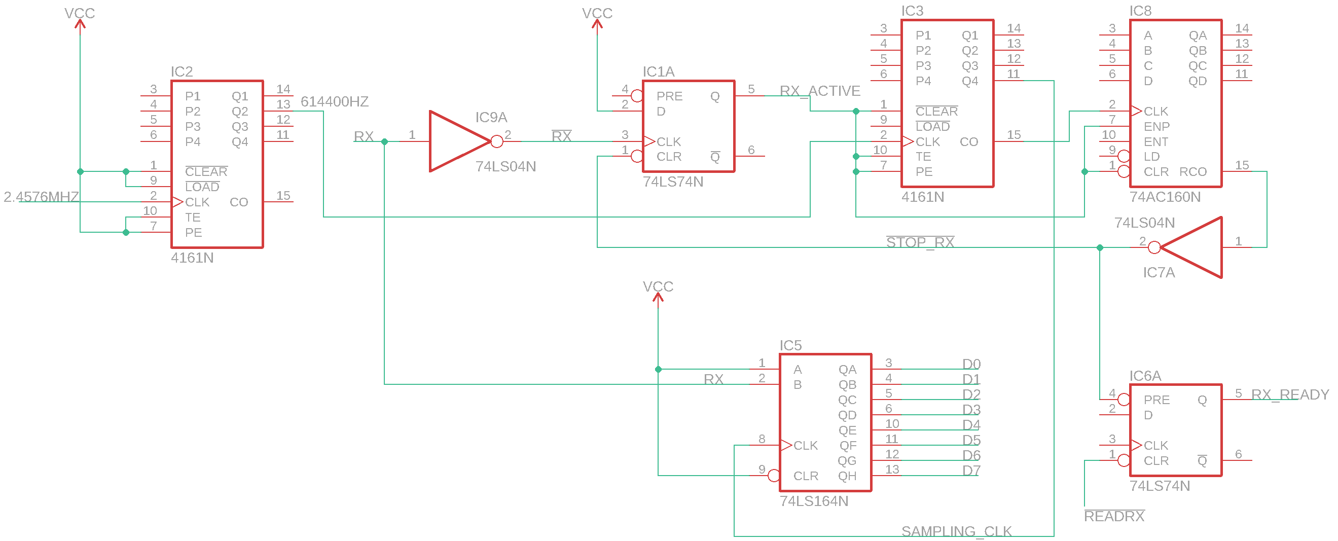
The waveforms in the bottom left of the schematic below indicate the timing considerations in receiving a single digital bit of the RX signal. How do we detect that there is an RX byte being sent? Quite easily in fact as the start bit of the RX signal is a high to low transition, so we can invert that and use the resulting low to high transition as a clock to set a D-flip flop (74LS74) (2).
Now we need to start recording the signal as it comes in, shifting it into shift registers and sampling at the centre of the data bit train. The most important idea to understand is that because we don't know when we are going to receive the UART data, it is going to be asynchronous with whatever clock we are running. Therefore the faster we make our clock, the closer we can get it to the true start of the RX signal. For convenience I am running a clock at 16 times the baudrate (1). That means each RX bit is 16 ticks of this clock wide. Therefore to sample the (approximate) middle of the RX data bit we need to sample the RX data line on the 8th count, so we generate the signal SAMPLING_CLK (3) to do this. On the rising edge of this new clock signal we can then clock in the RX signal to two chained 8-bit serial-in-parallel-out (SIPO) shift registers at the middle of each data bit (4). At the 16th count we have finished a digital bit, so we increment another counter, which tracks the total number of bits clocked in (5). When this latter counter gets to 16 (alternatively this could be a decade counter), the RX circuitry is disabled by clearing the D flip flop. Phew! The schematic is below and I hope the logic of the design can be traced through with my above commentary.

Unfortunately I don't have an oscilloscope, and the circuit gave some confusing results initially, where a byte would be received but the same byte again would be received differently. I switched out the 2.4576 MHz crystal oscillator for a 1 second period 555 so I could confirm the counting logic and found there was a problem with a floating input on one of the counter's clear pin (debugging with LEDs FTW). I tied both clear pins of the counters to the RX_active signal and this switches the counters between being enabled and being cleared, tidying up the counter outputs at the end of each receiving cycle. The counting now worked as expected, and when I put the 2.4576 clock back in, it worked correctly and robustly! Result!
The final design in the context of a breadboard computer will have an output register to control the output onto the databus. Lastly, I used the unused D flip-flop on the 74LS74 to implement an RX_READY signal, which could be read by a CPU to check if a byte is ready to read (it is only true when a byte has been fully read in).
Here it is again below, fully assembled and working. The UART-USB interface is the dongle on the top-right, the middle breadboard has the crystal oscillator and 4-bit counters for generating the various clocks with the 16-bit shift register on the top by the USB power supply. The left-hand breadboard has the logic for sending a single byte in a controlled way (i.e the UART TX). If you look closely you'll spot a button I used to simulate a CPU control signal, and a 555 oscillator to act as the CPU clock. On the right-hand breadboard the UART RX module lives, with the green LEDs clocking in the received byte, the yellow LED showing data is being received (ie UART RX is busy) and the red LED turning on when a byte is ready to be read by the CPU.
I need some neater breadboards, and some neater breadboard wiring skillz.
EDIT:UART RX UPDATE
I have optimised my design a little (and learnt a lesson about asynchronous vs synchronous events in discrete logic ICs along the way). I wanted to reduce the chip count by using a decade counter to count the incoming bits on the RX line, and by counting in 10 bits, rather than 16, I could therefore remove a shift register. Initially I tried a 74LS162 decade counter. While this did work for a single byte, I quickly learnt that it has a synchronous clear mechanism, meaning a clock cycle is required to clear the signal. As the clock is stopped as soon as the last bit is received, the counter is never cleared. The 74LS161 4-bit counter that this replaced, has an asynchronous clear, which is why this was working previously. Thankfully there is an asynchronous clear decade counter, namely the 74LS160. Using this instead works really nicely, as shown in the updated schematic below.
Error checking the received byte
For simplicity, I haven't added any error checking to the received byte. One could imagine including a parity bit and toggling a flip-flop every time a '1' is received. This would have the effect of assessing whether there was an odd or even number of data bits, which could then be compared against the parity bit, and a flag set if there was a mismatch. In addition, a check to confirm that the stop bit was '1' could also be incorporated into an error flag. For reasons of space I decided not to add these features, but I'm tempted to include them in the future. The modularity allows this to be added later if deemed necessary.
Update: Adding UART transceiver to the breadboard 8-bit computer...
 I have neaten up the wiring and incorporated the UART into the 8-bit breadboard computer that I'm developing, blog post here.
Remarks
I like 8-bit computers on breadboards and I enjoyed this mini-project. After thinking about the design for a little while, it was still a kind of shock when I put it together and it all worked. Logic, it's like magic, except it isn't.
I hope to blog about various bits of my 8-bit computer as I build modules for it. Let me know in the comments below if you enjoyed this or have any questions!


Congrats for the amazing work. Seen your post @ hackaday! Keep up the good wotk! Cheers.
ReplyDeleteThanks Marco, I really appreciate the positive feedback!
DeleteAwesome project, good job.
ReplyDeleteThanks for taking the time to say something nice Jake! It is really encouraging to me and much appreciated!
DeleteThanks for sharing this! A got here searching for ways to use PS/2 keyboards for retro-computer projects and your UART certainly can help a lot.
ReplyDeleteDid you tried something like a keyboard to test your UART?
Also.. May be of your interest that I took the freedom of liking this post into this stack exchange question specific about Z80:
> https://retrocomputing.stackexchange.com/questions/9382/how-do-i-interface-a-ps-2-keyboard-without-modern-techniques/16496#16496
.
Hi Everton, thanks for your comment and also for sharing my post! I tested my UART by hooking it up to a PC and then using Putty to type on my PC and then see the corresponding ASCII code appear on my UART breadboard. I also wrote a small python script to send characters in pretty patterns to verify it (i.e. in sequence from 0 to 255 and seeing it UART light up like a binary counter).
DeleteI have thought about making an PS/2 interface. What's nice about the PS/2 protocol is that the keyboard supplies its own clock, so one only has to latch in the data - in principle then a couple of chips could do the trick. I don't think the PS/2 clock is a standard UART baud rate that I could plug into this breadboard(?). Either the CPU attached to a PS/2 receiving breadboard could quickly poll any keyboard data when it came in, but the downside might be that data might be missed if the CPU was busy or two slow, for example if two bytes were received in rapid succession. What would be really cool was if there was some logic in the PS/2 receiving circuit to map the received key strokes into a bit of memory for the CPU to read at its leisure...
Everton, you might be interested in this PS2 controller built from TTL chips:
Deletehttps://github.com/DerULF1/8bit-computer/blob/master/Schematics/PS2Controler.pdf
as part of this 8-bit computer:
https://github.com/DerULF1/8bit-computer
Wow, very nice tip! Thanks Duncan, really exciting.
Delete(the only sad part is that some of this TTL will be hard to find available in my country)
A shame you have difficulty accessing the parts for this. I'm in the UK here and getting hold of chips has been *relatively* straightforward. I've yet to see what the effects of Br*xit will be that! I have some success with using Ebay and Mouser to find chips though with the former they tend to be a little more expensive than otherwise and with the latter, big electronic suppliers, they tend to have large shipping costs which means buying a whole load to make it worthwhile! I don't know if those are options in your country or not... I have seen chips available on the Chinese sites like AliExpress, but I haven't bought any from there yet. They look really cheap, but I'm often too impatient to wait 3-4 weeks for shipping and of course there is a risk they are not the real deal.
DeleteExcellent work. I am yet to test the circuits. It is useful in safety critical system where hard real time system is required.
ReplyDeleteNo it isn't useful in safety critical systems, much better to use the UART peripheral built into most microcontrollers. It is a proof of concept purely for educational purposes and to satisfy the challenge of an all TTL chip based UART for my 8-bit computer I'm building.
DeleteIt's very nice bro but are you can add radio transmission for your circuit or no?
ReplyDeleteThanks, I *could* make the UART transmit by radio I suppose, but I am not inclined to at the moment!
DeleteThis comment has been removed by a blog administrator.
ReplyDelete