PS2 controller as a radio controller!
Turning a PS2 controller into a wireless radio controller with Arduino Mini and an nRF24l01 radio module

http://fabioangeletti.altervista.org/blog/playstation-controller-hack-with-arduino-mini-n24l01/?doing_wp_cron=1560090015.5827820301055908203125
I have elected to use one of the "long range" nRF24l01+PA/LNA modules - which supposedly have a range of up to 1000 metres...! :-O I've switched to using an Arduino Mini module, using the Atmega328 AVR at 3.3V, primarily because of it's small form factor. I've also added a red LED that is controlled by the Arduino for a visual cue, and a USB port and charging circuit for a 1S LiPo battery. A green LED and yellow LED have been added to indicate the charging status, and a SPDT switch on the side controls the power. Finally I added a mini piezo buzzer to provide feedback about radio status, etc.

Some hacking required! Making room for the radio (Left) An area for the nRF24l01 radio was carefully hacked out and (right) the module was put into position.

(left) In order to provide a USB prot for battery charging, I also installed a mini-USB port using a breakout module similar to the image. See Power section for more detailed description of charging circuit.
Wiring
The key to interfacing with the PS2 controller is a header panel in the top left of the board - these are the wires that ordinarily connect to the output port. Therefore if we solder to these directly, it will be as if we had connected to the output socket. There is apparently some slight variation with the header pins between controller models, and the image below shows the pin assignment of my particular model. Fortunately however, the meaning of the colour coding of the original wires appears conserved between models. I de-soldered the original header to make sure I had a really good physical connection, and hooked it up to the Arduino Pro Mini pins as described below.


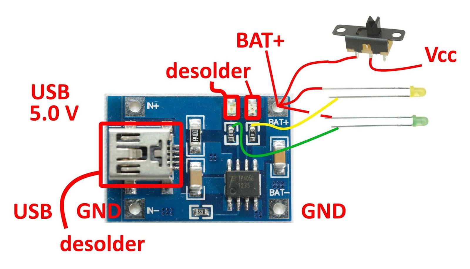
 (above) TP4056 charging circuit with a 1S LiPo battery. Some components were desoldered, LEDs were connected and a power switch attached.

Note that I added a small piezo speaker - it is a little under powered at 3.3 V but it adds a musical cuteness - I use it to report on radio packet acknowledgement status - a dull, low tone every second when the radio fails to send, and a musical trill when a radio packet is successfully sent. It is a much quieter now it is sealed in the controller, so I might have to create a hole for it to sing out of.
PS2 controller code:
On the receiver side, we just need a simple sketch that initialises the Mirf radio with the correct RX and TX addresses, enables ACK and then waits for a packet from the PS2 remote.
Interested in Arduino and AVR programming? You might also enjoy:
I have elected to use one of the "long range" nRF24l01+PA/LNA modules - which supposedly have a range of up to 1000 metres...! :-O I've switched to using an Arduino Mini module, using the Atmega328 AVR at 3.3V, primarily because of it's small form factor. I've also added a red LED that is controlled by the Arduino for a visual cue, and a USB port and charging circuit for a 1S LiPo battery. A green LED and yellow LED have been added to indicate the charging status, and a SPDT switch on the side controls the power. Finally I added a mini piezo buzzer to provide feedback about radio status, etc.
Choose your wire length carefully, and think about where the modules will end up in the housing. This hack is as much amount cramming everything into a tight space as it is about software and electronics!
Disassembly
First of all, the back of these controllers come off fairly easily with a few small screws. Some removal of the white plastic housing was necessary to accommodate the radio module. The hole that would ordinarily house the wires to the console was slightly enlarged to allow the radio antenna to stick out. I originally wanted to maintain one of the rumble motors, but it became clear as I was putting everything together that there just wasn't enough room inside, so both rumble motors were desoldered and the valuable real estate was reclaimed by cutting out the motor-supporting white housing.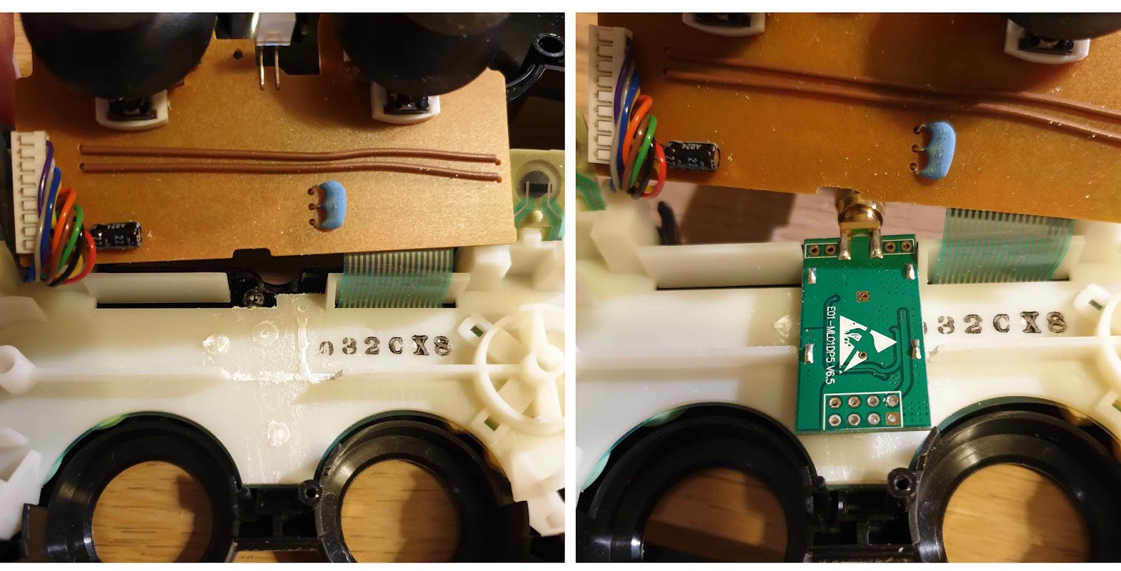
Some hacking required! Making room for the radio (Left) An area for the nRF24l01 radio was carefully hacked out and (right) the module was put into position.

(left) In order to provide a USB prot for battery charging, I also installed a mini-USB port using a breakout module similar to the image. See Power section for more detailed description of charging circuit.
Wiring
The key to interfacing with the PS2 controller is a header panel in the top left of the board - these are the wires that ordinarily connect to the output port. Therefore if we solder to these directly, it will be as if we had connected to the output socket. There is apparently some slight variation with the header pins between controller models, and the image below shows the pin assignment of my particular model. Fortunately however, the meaning of the colour coding of the original wires appears conserved between models. I de-soldered the original header to make sure I had a really good physical connection, and hooked it up to the Arduino Pro Mini pins as described below.

(Left) PS2 PCB with de-soldered header and new wires soldered. (Right) Connections from PS2 PCB to Arduino Mini pins
Choose your wire length carefully, and think about where the modules will end up in the housing. This hack is as much amount cramming everything into a tight space as it is about software and electronics! Next, I hooked up the radio module to the Arduino Mini, using the connection guide below:

(Above) nRF24l01 with header de-soldered and colour coded Arduino Pro Mini pin connections
As you know, all GNDs must be connected together
Power
Power management is always an important consideration. As space is at a premium inside the controller, I have used a pretty tiny 1S LiPo battery, and modified a TP4056 charging module as described below. The "resting" voltage of a 1S LiPo battery is 3.7 V, fully charged it is 4.2 V and about 3.3 V at the lowest charge. The Arduino board is clocked at 8 MHz, and should be able to go up to 5.5 V without issue. Strictly speaking, I am running the nRF24l01 module out of spec as it is a 3.3 V module, but it doesn't appear to be an issue to run at 3.3 - 4.2 V... I am potentially taking a risk by putting this voltage range into the PS2 controller (rather than 3.3V), but again, no problems have been evident. I could/should have used a low voltage dropoff 3.3V linear regulator (the MCP1700-3302E perhaps).
The TP4056 module USB port was desoldered (to save space), and the IN+ and IN- were connected to VBUS (5.0V) and GND of the mini-USB port breakout module. Further, the two charge indicator LEDs were removed and 3 mm yellow and green LEDs were connected. Finally BAT+ and BAT- were soldered to the battery VERY CAREFULLY, ACCIDENTAL HEAT ON A LiPo BATTERY CAN CAUSE FIRES! The Vcc from the switch was connected to Vcc of the rest of the circuit - i.e. to power the Arduino, PS2 PCB and nRF24l01 radio module.
The final layout
Finally when everything is correctly soldered and connected, it looks something like this:
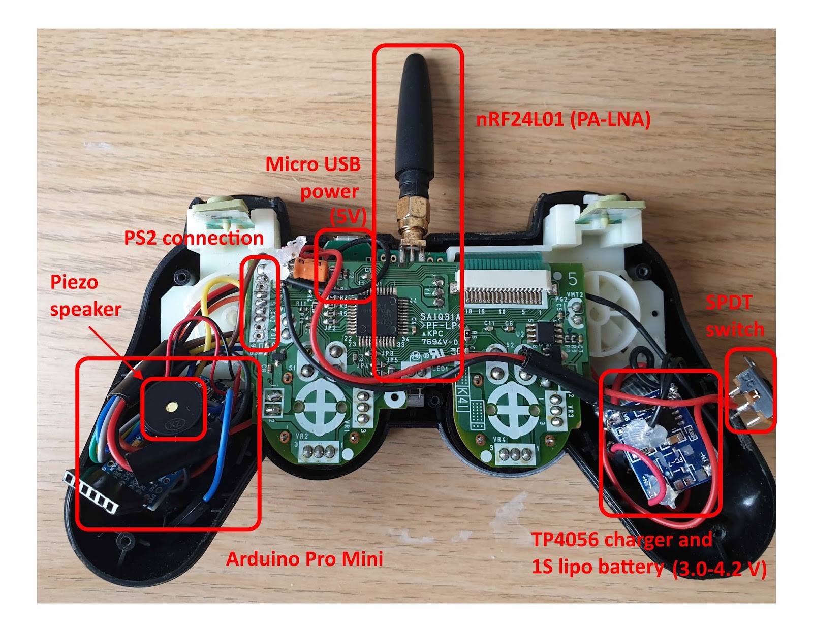
Note that I added a small piezo speaker - it is a little under powered at 3.3 V but it adds a musical cuteness - I use it to report on radio packet acknowledgement status - a dull, low tone every second when the radio fails to send, and a musical trill when a radio packet is successfully sent. It is a much quieter now it is sealed in the controller, so I might have to create a hole for it to sing out of.
Software
The software to run on the PS2 controller is fairly straightforward. We'll need a PS2 controller library from here and the Mirf radio library from here. We setup the radio module (with ACK acknowledgements enabled), then the PS2 controller (the code is inherited directly from the PS2 library example). In the main loop, we read the PS2 buttons, assemble a radio packet and attempt to send it. If we detect that we've successfully sent the packet we increment a count and every second output to a debug serial and making a corresponding beeping sound. Note that I needed to change the way the Mirf library sends data so that I can intercept the ACK flag in the STATUS register before it is reset.PS2 controller code:
On the receiver side, we just need a simple sketch that initialises the Mirf radio with the correct RX and TX addresses, enables ACK and then waits for a packet from the PS2 remote.
References
http://fabioangeletti.altervista.org/blog/playstation-controller-hack-with-arduino-mini-n24l01/
https://dlnmh9ip6v2uc.cloudfront.net/datasheets/Prototyping/TP4056.pdfInterested in Arduino and AVR programming? You might also enjoy:
 ATtinyMario
- Adding LCD character display to Attiny85
- Decoding and sending IR signals with an Arduino Nano
- Controlling quadcopter with PS2 controller
- PS2 radio controller - NEW!


Please help me arduino nano ch340g ps2 controller coding in issu ps2x_lib.h but not install these file
ReplyDeleteYou'll need to install the libraries described in the blog post (see "software" section).
DeleteDo you know how to install Arduino libraries in general? If not follow these instructions:
https://www.baldengineer.com/installing-arduino-library-from-github.html
Hope that helps you.