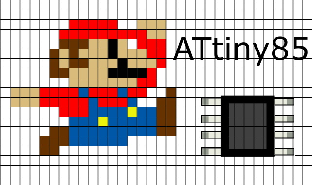
ATtiny Mario
ATtiny85 Mario Challenge!
The ATtiny85 microcontroller is a capable but compact AVR. However with only 8K of program memory, 512 bytes of EEPROM, 512 of SRAM and only 8 pins (3 of which are dedicated to the usual suspects of Vcc, GND and RESET), it best suited to performing tasks where memory demands are not large, and only a few pins are required for interfacing.
- Use only the ATtiny85 as a microcontroller - no offloading the heavy lifting to other chips!
- Though perhaps using other ICs to expand the GPIO pins might be acceptable (i.e. the PCF8574 or PCF8574a, I've opted to consider that cheating! 😊
- Creative use of GPIO pins to maximise functionality strongly encouraged
- Cram as many features into 8K of program memory and 512 of SRAM as possible!
The aim here is to learn about the ATtiny85 chip and do something fun with it. If I wanted a proper Mario clone I could use a Raspberry Pi, an STM32 or even an ESP32 emulator - but where would be the fun in that?!
Some of the features I ended up implementing that might be of general interest are:
- Two OLED 128x64 screens and graphics.
- 3 button input on a single pin, with deconvolution of button combinations (Twice = 6 digital GPIOs on 2 pins).
- Dual tone music and sound effects by hacking 8-bit Timer0 for additional tone functionality
- Horizontal scrolling and procedural level generation (ad infinitum)
- Internal clocking of ATtiny85 at 16 MHz without external crystal.

Starting simple: Using an Arduino Nano with the screen
It turned out to be very straightforward to use an Arduino Nano (ATmega328p) hooked up to the SSD1306 screen using the Adafruit SSD1306 library. You'll also need to install the Adafruit GFX library to get the examples working. Arduino libraries can be installed by download the libraries as ZIP files and in the Arduino IDE, Sketch --> Include Library --> Add .ZIP library and select the downloaded ZIP file to install.
ATtiny85 OLED control using Tiny4KOLED library
You will notice the information for the Adafruit SSD1306 library explicitly stipulates that the library will not work with the ATtiny85 AVR. No matter though [datacute], has written the Tiny4KOLED library. These displays come in a variation of sizes and the Tiny4KOLED library is specifically for a 128 x 32 pixel resolution screen. Interestingly, the 128x32 screens have 128x64 memory available to them, and a really neat feature of the Tiny4KOLED library takes advantage of this to implement a flicker-free "double buffer".
My screen is a 128x64 pixel version, and unfortunately means that we don't have the surplus memory of the 128x32 screen to perform double-buffering. Thankfully, the library is relatively easily modified to support 128x64 screen, albeit without double-buffering. Specifically:
#define SSD1306_PAGES 4must be changed to:
#define SSD1306_PAGES 2And we need to change the screen initialisation sequence as below (in Tiny4kOLED.cpp):
static const uint8_t ssd1306_init_sequence [] PROGMEM = { // Initialization Sequence
 0xC8,   // Set COM Output Scan Direction
 0xA1,   // Set Segment Re-map. A0=address mapped; A1=address 127 mapped.
 0xA8, 0x3F,  // Set multiplex ratio(1 to 64)
 0xDA, 0x12,  // Set com pins hardware configuration
 0x8D, 0x14  // Set DC-DC enable
};
As we only have one screen we can write to (and not double-buffered), we must remove all references to oled.switchRenderFrame(); and oled.switchFrame(); in setup() and loop().
The Tiny4KOLED library communicates by I2C with the screen; there are 3 options (actually there is a fourth, better option but we'll come to that):
- Spence Konde's Wire.h that comes with ATTinyCore
- Adafruit's TinyWireM
- David Johnson-Davies / Technoblogy's TinyI2C
- ATTinyCore: 6736 bytes program (82%), 461 bytes SRAM (90%)
- #define TwoWire_h
- TinyWireM: 6460 bytes program (78%), 440 bytes SRAM (85%)
- Default library
- TinyI2C: 6200 bytes program (75%), 420 bytes SRAM (82%)
- #include <TinyI2CMaster.h>
- #define TinyI2CMaster_h
Second spoilers! Later still we will learn that we want to replace Tone completely to use both Timer0 and Timer1, and end up ditching the tiny core support in the Arduino IDE completely.
Pleasingly the TinyI2C library saves us 7% program memory and 8% SRAM! As we make the program more advanced, this could be crucial. We can have a near 100% full program memory, but not SRAM (variable memory), as we will need some saved for the stack (at least 100 bytes). For this reason I have used PROGMEM extensively where possible to store graphics, music and sound effects.
ATtiny85 Super Fast OLED display!
In fact there is a better way to implement I2C, and it's very fast with SSD1306 OLED screens. Following the work of [bitbanksoftware], I copied a bit-banged I2C procedure. I had to change it a little so it was robustly compatible with the changing PORTB pins for the music, and I added some explicit assembly. The speed increase was amazing! In fact I was now able to run TWO OLED screens at once! Because the I2C protocol uses the same bus, I can now drive two screens with no extra GPIOs. There is an address selector resistor on the reverse of the modules - I desoldered and resoldered it on one of the boards, which allowed me to address the boards uniquely.
Graphics, Mario sprites and animations

The screen is addressed as above, with an x-axis coordinate(column) and a y-axis "page" (row). Note, that 8 pixels are written at once to a page - it is not possible to address a single (x,y) pixel individually without affecting the 7 other pixels in the y-axis PAGE. Images for the screen addressing are from electronicwings.com. One strategy could be to read the column byte from the screen, however there is no "read pixel" protocol with I2C.
By chance I came across this post about using Mario sprites for pixel art on these displays. Inspired, I downloaded the pixel art for Mario and wrote a small function to plot a sprite, using these arrays. To save SRAM, I decided to store the sprites in PROGMEM and access with pgm_read_byte. Because I have configured the OLED screen with (0,0) in the top left and the sprites (XBM encoded as a byte array) for a different screen axes configuration, I had to rotate the 16x16 XBM data arrays with a custom Python script. Which results, pleasingly, in the Mario sprites being correctly displayed:

Plotting the screen
If we divide up the 128x64 pixel screen into 8x8 pixel blocks, we have a resolution of 16x8 blocks. If we either have a block at a position on the y-axis or not-a-block, we can encode an entire vertical column of blocks with 8 bits...a byte. This means we can hold the entire screen, represented by blocks, in 16 bytes! We can then look at the position of each bit in each byte to decide whether to draw a block or not. You'll notice different types of blocks in the levels. Per column, this is still encoded by a single byte, but there is some control logic that looks at the blocks surrounding the block and can decide to draw a different block depending on the block context. For example, if a bit is TRUE in the top row, a rotating coin is placed above the first platform below it!

To generate the necessary XBM image format, I did the following:
- Draw block in black and white in 8x8 image using Paint.net. White at this stage is where we want to draw a pixel on the OLED.
- Invert colours (black will become white and vice versa)
- Rotate the image 90 degrees counter-clockwise
- Save as a PNG image
- Use a program or an online utility to convert PNG to XBP.
- Open XBM image in notepad and copy out the hex data between { }; and paste into header file for sketch (i.e. bricks.h, mario.h, etc).
Similarly with Mario, as he walks leaves a trail of pixels, so this is wiped away by with drawing a black rectangle in his previous position - this is much fastest and allows me to write to two OLED screens at once.
Input controls
I've opted to use a voltage divider with carefully chosen resistors to allow me to detect multiple buttons pressed at once on a single pin. In the schematic below, buttons 4 to 6 are read through a single pin (PB3), which is pulled to ground via a 1k ohm resistor. Buttons 4 to 6 are then wired in such a way that when they are pressed, Vcc is connected via resistors R6 to R8 respectively. The resulting voltage divider through R1 has the special property that we can detect multiple button pushes simultaneously by reading the analog voltage at PB3! Buttons 1 to 3 operate in a similar manner on the RESET pin, but the voltages are reversed - R2 pulls the pin high so that the ATtiny85 isn't reset when a button is pressed and buttons 1-3 are connected to ground via resistors R3-5 when activated.

Random aside: I find Arduino pin numbering maddening sometimes! How IC pin 3 is also Arduino pin 4 and also Arduino analogue A2 is a recipe for pure confusion!Next I pressed the buttons to generate all 8 combinations of three buttons being either ON or OFF and measured the analog voltage on the pin. Typically, a 10-bit value is measured, scaling from 0-1023 where 1023 is the Aref voltage. The tabulated data is below, and a graph of the button combination code vs measured voltage (or rather the 10-bit ADC value).


#define buttonBASE 22
.
.
.
sensorValue = readADC(ADC3);

buttons = (sensorValue + (buttonBASE / 2)) / buttonBASE;
Nice! Now we can read one of three buttons, from a single pin, and by examining the bit pattern of "buttons", we can register the individual button presses.
Mario music
A quick google of "Mario ATtiny85" revealed a project that used an ATtiny85 to play the Mario theme music, and helpfully provided the notes and durations in their code. However, they weren't able to fit the whole theme tune onto the AVR due to limited SRAM. Taking this code as a starting point, and storing the score in PROGMEM it was trivial to adapt the code, based on the Arduino ToneMelody example, to easily fit the entire score. In fact I finally decided to use the 512 bytes of EEPROM on the ATtiny85 to store the music and sound effects, freeing up that precious SRAM. Although writing to EEPROM is relatively slow, it turns out reading from EEPROM is basically as fast as SRAM, so there are minimal performances concerns to read from the EEPROM. The EEPROM was written using a custom program running on the ATtiny85, though I could have used generated a binary file and burned it to the EEPROM using AVRDUDE or hacked the Arduino IDE. During testing it was convenient to retrieve the EEPROM memory from the chip to inspect that writing had gone smoothly. Using avrdude on the command line:
avrdude -c tinyisp -p t85 -U EEPROM:r:eeprom.bin:r
Note: I found that I had to use ATTinyCore in order to get tone() to working correctly with the ATtiny85 - the default core doesn't work. Although I didn't use ATTinyCore or tone() ultimately, I leave this comment here in case it is helpful to others.
I also needed to set EESAVE in High FUSE to retain EEPROM during re-programming --> High fuse = 0xd7 (rather than 0xdf). Not doing this meant the EEPROM got wiped when flashing the main program. I can read the ATtiny85 fuses using avrdude:
avrdude -c tinyisp -p t85 -U lfuse:r:-:i -U hfuse:r:-:i -U efuse:r:-:i
and write the ATtiny85 hfuse to 0xd7 with:
avrdude -c tinyisp -p t85 -U hfuse:w:0xd7:i
I converted the code to play the whole theme music with the music conveniently split in sections in different arrays and reading from EEPROM. Further, the code was upgraded to run in a non-blocking fashion and is called in every frame to check whether we need to change note or pause or whatever. Finally sound effects were added, which I configured to stop playing the music, play the sound effect, then start playing the music again (in fact the music wasn't paused, just silenced, so that the rhythm wasn't lost). I thought it would be cool to have an independent tone generator, and then with either two speakers or hardware mixing, have independent music and sound effects! On the ATtiny85 we have two 8-bit timers. The tone() library utilises Timer1. Timer0 is left untouched for use with delay() and millis(). Can we use timer0 to give us a second tone generator?
Timer0 tone generation
I wanted to configure Timer0 as a tone generator, which was relatively easy to implement using the CTC PWM mode. The only 'gotcha' was when I recalled that my tone controller code relied on millis() (and therefore timer0) to correctly implement the length of notes and pauses between notes. The solution is inspired from the tone() library, and is to calculate how many oscillations will occur during the note at a certain frequency and duration, and then have an interrupt count down the oscillations. When the count is 0, the note is finished. Cunningly, I could also implement a milli-type timer by simulating a tone, but disabling the hardware output and using the counting down function. This worked pretty nicely. See the code in main.c on github for details of my code (specifically mytone()) .
Because music is always playing, either a musical tone or a pause (silent tone) is being played using Timer1. Therefore, by knowing what the period is of the pin toggling in the Timer1 ISR, I can hack an approximate microsecond timer by keeping count of elapsed timed cycles in the ISR like so:
mymicros += ISR_micro_period;where ISR_micro_period is calculated at each invocation of mytone():
ISR_micro_period = 500000L / frequency; // 1E6 / (2*frequency), because ISR is called 2 times every period.This means I can use 'mymicros' to do timing elsewhere, such as keeping a steady frame rate. It's a hack, but hacks are good :-)
Clocking ATtiny85 at 16 MHz internal
Although the slow step appears to be updating the OLED display every frame, it certainly doesn't hurt to increase the ATtiny85 clock speed. I was clocking at 8 MHz using the internal clock, and to get 16 MHz clock speed it is usual to have an external crystal oscillator. That's two pins that we can't afford to spare! However it is possible to configure the Attiny85 to run at 16 MHz purely using the internal clock following this guide. As I put the music and sound effects into EEPROM I needed to also program the EESAVE bit in the high fuse - in the case of configuring for a 16 MHz internal clock, the low fuse = 0xF1 and the high fuse is set as 0xD7. It is even possible to run at 20 MHz internally.
Miscellaneous and conclusions
This was a project where program memory and SRAM constraints were constantly on my mind. The limited GPIO pin also offered unique challenges. In conclusion, techniques I employed to work within these constraints, were:
- Elimination of floating point maths where possible; Floating point on these chips can come with a surprising memory overhead.
- Faster implementation of some Arduino library functions (such as reading and writing pins)
- I eventually transferred the project from Arduino IDE to Atmel Studio 7.0; although the saving here actually wasn't large in terms of memory, it did allow me to break up some of the code into multiple files more conveniently, so I stuck with it.
- Internal clocking without a crystal; saves 2 GPIOs
- Up to 3 digital buttons on a single GPIO, including on the RESET pin.
- Timer0 and Timer1 hijacked for music and sound effects and a hacked micros() type function implemented.
- Fast OLED I2C bit banging protocol is fast and compact; allowed for two independently addressed screens to be run at once.
- Judicious use of PROGMEM throughout.
- Putting music and sound effects into EEPROM.
- Procedural map generation, inspired by Squario, on the Arduboy
- The code for this project is fully available here: https://github.com/shepherdingelectrons/ATtiny85Mario
UPDATE
I have now completed the controller and written it up Part 2 here. Here is the video of it in action:In case you wondered why the music speeds up and slows down at a certain point in the video, it's intentional, and because I've coded the music tempo to speed up at 10 coins collected and revert to normal at 20 coins. I was playing around with a way of using the same musical score to indicate power-ups, etc but it's not something I explored any further :-) Happy hacking! :)


This comment has been removed by a blog administrator.
ReplyDeleteThis comment has been removed by a blog administrator.
ReplyDeleteThis comment has been removed by a blog administrator.
ReplyDelete