8-bit Computer: Adding the UART modules
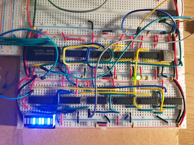
Until now, my UART transceiver module existed across three breadboards and was not integrated into the 8-bit computer, see previous post. I have now added my UART module to the 8-bit breadboard computer I am building. I have modified the design slightly by adding an 74LS245 so that the received byte can now be put out onto the databus. The blue LED bar below shows the current received byte, and the green LED is lit when
Updated schematic
The UART TX module remains as previously described, but the finalised UART RX schematic is updated below. Notably a 74LS245 chip can now control the output onto the databus.
Chip geography
In terms of placement of the chips to make as logical and clean layout as possible, I have used the following layout below. The transceiver spans 2 breadboards, and borrows an AND gate (74LS08) from what will be the FLAG register.
Coming next, the ALU and the FLAG register!


I just wanted to say thank you very much for your post. I am heading down the exact same route with building my 8-bit cpu and most definitely was looking for uart inspiration.
ReplyDeleteYou are very welcome and thanks for taking the time to stop and say something nice, it encourages me too! I use this blog mainly as a way of recording things I've learnt and projects I've made, mostly so I don't' forget them or how to do something... it is a very cool that someone else can find inspiration here! :) If you have a blog or website, it would be cool to see what you do with your 8-bit computer as it develops :)
DeleteI'm also building a UART (from 4000 series chips, I have lots), so your article has been great source of help, many thanks. When connecting to the CPU bus, how have you dealt with conditions such as:
ReplyDelete(1) Writing a new byte to the TX circuit whilst it's in the middle of transmitting the previous byte.
(2) Reading a byte from the RX circuit whilst a new byte is being received.
Hi Stuart, thanks for your comment. I'm typing this on my phone so a little limited but to answer your questions:
Delete(1) see here:
https://1.bp.blogspot.com/-NgzI07BMbZY/Xx86480EcrI/AAAAAAAABAQ/Tdh1mqZ4utwfSFKy2WcUKq-YaBftMlRQgCLcBGAsYHQ/s2048/UART_TX%2B7400%2BICs.jpg
This is the transmission schematic from here:
https://shepherdingelectrons.blogspot.com/2020/07/uart-transceiver-for-breadboard-computer.html?m=1
The "SENDING" signal can be fed into a CPU status byte and checked before deciding whether to send the next byte.
(2) I haven't implemented any buffer system to my RX circuit, but I have a signal "RX_READY" that indicates when a byte is ready in the RX. Of course, it is still a problem if another byte is sent as this is being read. I rely on the other connected UART to only send another byte when the CPU sends an acknowledgement, such as echoing the received byte back.
Hope that helps!
It is a great circuit of having TTL setup like from scratch. But how are u giving the clock signal of 2.4576Mhz to the 74LS161 like from where are u generating it from is my question is there a circuit diagram for it. I am a bit of noob here u can think
ReplyDelete