Posts

Showing posts from May, 2016

4 x 16 bit servo control on Atmega328p

Image
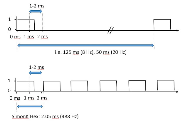
Controlling four motors with Atmega328 Timer1 One of the challenges in a quadcopter project is to correctly control the four thrust motors, via ESCs.  The control is effected by a pulse between 1-2 ms.  In ESC controllers, the refresh rate can be as low as 8 Hz or 20 Hz.  In quadcopters this refresh rate is far too slow - I have seen 100-200 Hz suggested as a suitable update frequency.  The "SimonK" hex is often reflashed to ESC controllers, as it has a refresh rate of approximately 488 Hz, very close to the theoretical refresh limit of just below 500 Hz. Algorithm idea Using the Atmega328 chip, we have only one 16-bit timer available, Timer 1.  Of course there are two other timers, but they are 8 bit timers, and I really want to stick to the resolution of the 16-bit timers.  We could consider using an AVR with four 16-bit hardware timers and use the four timer output pins, but it is interesting to see what can be done with just one.  So we are having to do the job

Programming Atmega328p chip wirelessly with nRF24L01+ module - Part II

Image
Fitting nRF24L01+ code into a bootloader A brief follow up to an earlier  post .  I previously had a system working whereby I was able to program an Atmega328p chip, using a connected Arduino Nano, but crucially using an nRF24L01+ module rather than a wired UART/PC connection.  What I really wanted however was to remove the Arduino Nano, and to program the MCU chip 'directly' by use of a bootloader with nRF24L01+ code to replace with the usual UART functionality.  I thought initially that I wouldn't be able to cram the radio module code into a bootloader, but in fact it wasn't too difficult.  I used Optiboot as a starting point and implemented bi-directional radio control within the bootloader.  I think it ended up being less than 1024 words (2048 bytes). I'm not an expert here - but I had to modify the compiler and linker parameters to get things to work: Compiler flags: -g -Wall -Os -fno-split-wide-types -mrelax Linker flags: -Wl,-section-start=.tex

Disassembling Arduino generated code

Image
Johnny Five... No disassemble! I recently had need to work out how many clock cycles certain functions in my code took to execute, so it was time to find the HEX file and disassemble back to the ASM instructions.  In the Arduino environment you are shielded from getting your hands dirty with the generated compiler files, but they can be located in a temporary directory in Windows, found under: C:\Users\ USERNAME \AppData\Local\Temp\build XYZ .tmp where " USERNAME " is your ... user name and XYZ is some long integer that Arduino comes up with.  Make sure you have recently compiled your code in Arduino - the folders are deleted or wiped when you exit Arduino.  In this folder you'll find some interesting files, among them the .HEX file and .ELF files are of particular interest.  Either make a .BAT file or use the CMD prompt to execute the following commands. Disassemble from HEX We'll use avr-objdump, but we need to specify the architecture.  Find the ne