Bluetooth programmer
From breadboard to perfboard
I have been busy bending Bluetooth modules to my will. The typical parameters I need to control are the module name, baud rate, and whether the module is a slave or master. To program my quadcopter over Bluetooth, I have defined a Bluetooth module as a Master, which connects automatically to the quadcopter slave module when available. The Master module connects to the PC via an RS232 USB converter - until now this been a mass of wires living on a breadboard, but I've now finally soldered a simple circuit together to allow me to program modules more easily.
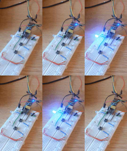
Above: The circuit in action. The closest module is communicating with the PC. The yellow wire is soldered to Pin34 and can be connected to 3.3V (right hand set of 4 pins) to enter AT-mode. The module at the back is a slave module and is powered but not communicating. LEDs indicate connection status.
Some features of the circuit are:
- HC-05 RX line needs a 5v --> 3.3v voltage divider (connects to RS232 USB TX)
- The 3.3V bus is broken out in order to connect Pin34 for AT mode (see blog entry here)
- LED shows connected status of main module (green LED)
- The socket on the right is for powering a second module, but RX/TX are not connected. This is useful for setting up pairing behaviour when it is required that both modules are powered.
- LED shows connected status of secondary module (red LED)
For the record, the LED resistor is 100 Ohms, and the voltage divider is composed of 10 kOhm and 20 kOhm resistors. A simple and quick build, but I'm sure it will be a very handy circuit for programming Bluetooth modules in the future!


Comments
Post a Comment