Getting started with the Pro Micro Arduino Board
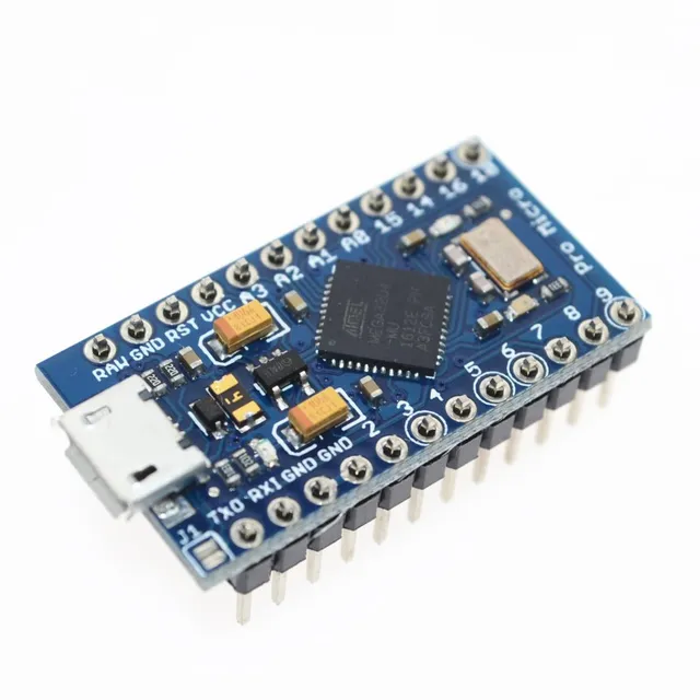
This is a cute but pretty powerful board - the Atmega32U4 has hardware USB support, meaning it is very easy to turn this little board into a keyboard or mouse device. The Atmega32U4 is a pretty capable AVR - the datasheet is here.
When you first plug the Pro Micro board in, the COM port may not appear in the COM port list in the Arduino IDE. Fear not! We just need to install the driver correctly. In Windows, open Device Manager and navigate to Ports (COM & LPT). It should read something like 'Arduino Leonardo' (that is how the device is recognised, also based on the Atmega32U4 chip). If things aren't working, there will be a yellow exclamation mark besides the Arduino Leonardo text. Right click on this and select "Update Driver Software" and "Browse my computer for driver software". Browse to your Arduino installation directory, something like "C:\Program Files (x86)\Arduino" (or whatever it is on your computer) and make sure "subfolders" is ticked. Click OK and the driver should install (it can take a while). In the Arduino IDE you should see a new COM port available (under Tools) - if not try restarting the software and confirming the "Arduino Leonardo" device appears in Device Manger without a warning exclamation mark.
Uploading a modified Blink sketch
The Pro Micro board, unlike many other Arduino boards, doesn't have a dedicated built-in LED. The standard example Blink sketch therefore, WILL NOT APPEAR TO WORK! But also, unlike other Arduino boards, there are two LEDs on the serial RX and TX channels, that we can control and flash. Therefore the Blink sketch can be updated to the code below to flash these RX and TX LEDs.
int RXLED = 17; // The RX LED has a defined Arduino pin
int TXLED = 30; // The TX LED has a defined Arduino pin

// the setup function runs once when you press reset or power the board
void setup() {

  pinMode(RXLED, OUTPUT); // Set RX LED as an output
  pinMode(TXLED, OUTPUT); // Set TX LED as an output
}

// the loop function runs over and over again forever
void loop() {
  digitalWrite(RXLED, HIGH); // set the LED off
  digitalWrite(TXLED, LOW); // set the LED off
  delay(300);                       // wait for a second
  digitalWrite(RXLED, LOW); // set the LED on
  digitalWrite(TXLED, HIGH); // set the LED on
  delay(300);                       // wait for a second
}
Now you are set up to start using the Pro Micro board!Serial UART Tip
You can get started with Serial communication right away, even if you haven't soldered on the headers yet as it is handled through the USB port. Just call Serial.begin(9600) in setup() and then Serial.print("message") as usual - note this will interfere with the RX/TX LEDs. If you want to communicate with the RX/TX lines that are broken out on the board, i.e. DO (TX) and D1 (RX), simply replace all calls to Serial with Serial1.
References:
https://learn.sparkfun.com/tutorials/pro-micro--fio-v3-hookup-guide/all
http://ww1.microchip.com/downloads/en/devicedoc/atmel-7766-8-bit-avr-atmega16u4-32u4_datasheet.pdf


This comment has been removed by the author.
ReplyDeleteThank you very much, this was helpfull.
ReplyDeleteThe normal Blink Sketch doesent work on an ProMicro.
I finally figured out that the RX and TX LEDs are also inverted. That is setting to LOW turns them ON, setting HIGH turns them OFF.
ReplyDelete