This is part of a series on the build of my 8-bit computer.
Registers and LED outputs
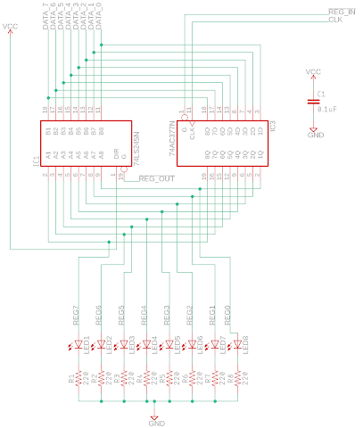
Registers are an essential part of a CPU. In my 8-bit computer build, I want to sneak in as many LEDs (blinkenlights) as possible to indicate the 8-bit values held in various registers, not only useful for debugging but also because it looks friggin' cool. For my A and B registers, which will feed into the ALU, I'm using a 74LS245 as an output latch, and the 74LS377 D-type flip-flop to set the value of the register. Note that the 74LS377 is an 8-bit version of the 4-bit 74LS173, which I would have to use two of to have an 8-bit register. The schematic for each register is pretty straightforward, see below:
For the LED output, I decided to use these LED bar displays with a 220 Ohm SIL resistor pack. To save on breadboard space, I decided to try and fit both the A and B register on the same breadboard, along with an LED bar displays for each register. With the 4 ICs and the 2 LED bar displays, this corresponds to about 6 ICs worth of space, a very busy breadboard!
Above: That A and B register is crammed! The A and B registers are each hooked up to red LED bar displays. Below them, is a blue LED bar display that is hooked up to the data bus.
Given the sequential alignment of the A1-A8 pins on the register-side of the 74LS245, I decided to create a little LED bar display module that can be just plugged appropriately below the 74LS245. Also because the 74LS245 has a ground pin at the bottom right (pin 10), this can be lined up conveniently with the common ground of the SIL resistors.
The 220 Ohm SIL resistors were soldered to the cathode to the LED bar display, and then the legs of LED bar display that correspond to the 8-bits of the register were snipped off. The LED bar displays can then be plugged just below the 74LS245, with the SIL resistor side going straight into the ground rail.
Now with the plug-in LED bar displays there is much more space on the A and B register breadboard,
and it is now much easier to plug in these modules wherever I'll need them on the rest of the computer! This means that I don't have to wire in the display modules, I just push them in.
Next up, making an ALU for the computer.


This comment has been removed by a blog administrator.
ReplyDelete