Programming Atmega328p chip wirelessly with nRF24L01+ module - Part I
I recently got my hands on a bunch of nRF24L01+ modules. They're really easy to use and dirt cheap to pick up. I followed this tutorial, which uses maniacbug's fantastic arduino library. Although they are fairly ubiquitous as a radio transceiver of choice, I first heard about them on the excellent Julian Ilett's Youtube channel:
I'm actually new to Arduino, but have messed about with programming chips and designing electronic devices for a couple of years. I can see the attraction of Arduino, and I can see it's a great gateway for more fundamental electronics. I picked up a couple of Arduino nanos (well, cheap Chinese knockoffs - they worked fine, incidentally), plugged them into the radios and installed some transmitting code on one (the joystick TX example in the tutorial) and some receiver code on the other - they worked great, out the box first time!
Well that was just too easy! The range was impressive too, at least twenty metres from the bottom of my backgarden to the front of the house - hey, I was impressed anyway. It got me thinking what you could do with such nifty things. I've got a quadcopter in the works (once the other projects are done...) and I'm sure they will feature plugged into the custom PCB for control and telemetry info. I saw The Martian recently - I think I remember reading somewhere that NASA can actually reprogram their probes remotely. Well, that sounds like a challenge! Could these radio modules be used for such a purpose (well across the room, rather than the solar system)? There are Xbee/Zigibee solutions for Arduino's I suppose. I could say that they are expensive and this is a cheaper alternative, but really... I just like to do these things because I want to learn and it is a challenge, rather than having perhaps solving a real, never before approached problem!
I'm used to programming AVR chips with my ISP (using my USBtinyISP programmer) and avrdude, and it turns out Arduinos can be coaxed to program other Arduinos, using the breakout ISP header and flashing them with the "ArduinoISP" program in the included examples with the Arduino software. The program works by receiving serial data from the PC (RX/TX) and then using SPI serial (MOSI/MISO/SCK/RESET) to program the slave Arduino/chip. So here's what I did:
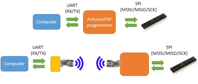 Basically I have one Arduino nano which listens to the Serial port on the computer and then transmits and receives data. The other Arduino is a modification of the "ArduinoISP" program; it listens to the radio signals it receives and programs the chip accordingly. This guy below is the PC-side Arduino nano (the yellow rectangle in the above figure)
 The code that runs on the above Arduino is as follows:

The modified ArduinoISP code which is hooked up to the chip/Arduino to be programmed is as below (the orange rectangle in the figure):
avrdude -P COM7 -p m328p -c avrisp -b 19200
Where COM7 is the particular COM port that the Arduino is plugged into. The target chip 'm328p' indicates of course the Atmega328p AVR. The baudrate is 19200 bps and 'avrisp' tells avrdude to expect the device on COM7 to behave like an AVRISP.
The chip is read as expected! Next, I can erase and program the chip wirelessly using:
avrdude -P COM7 -p m328p -c avrisp -b 19200 -e -U flash:w:MyBlinkslave.cpp.hex
Where 'MyBlinkslave.cpp.hex' is the hex file generated by compiling in Atmel Studio or output from the Arduino GUI (you'll find it in Windows under AppData/Local/Temp/build****).
I'm actually new to Arduino, but have messed about with programming chips and designing electronic devices for a couple of years. I can see the attraction of Arduino, and I can see it's a great gateway for more fundamental electronics. I picked up a couple of Arduino nanos (well, cheap Chinese knockoffs - they worked fine, incidentally), plugged them into the radios and installed some transmitting code on one (the joystick TX example in the tutorial) and some receiver code on the other - they worked great, out the box first time!
Well that was just too easy! The range was impressive too, at least twenty metres from the bottom of my backgarden to the front of the house - hey, I was impressed anyway. It got me thinking what you could do with such nifty things. I've got a quadcopter in the works (once the other projects are done...) and I'm sure they will feature plugged into the custom PCB for control and telemetry info. I saw The Martian recently - I think I remember reading somewhere that NASA can actually reprogram their probes remotely. Well, that sounds like a challenge! Could these radio modules be used for such a purpose (well across the room, rather than the solar system)? There are Xbee/Zigibee solutions for Arduino's I suppose. I could say that they are expensive and this is a cheaper alternative, but really... I just like to do these things because I want to learn and it is a challenge, rather than having perhaps solving a real, never before approached problem!
I'm used to programming AVR chips with my ISP (using my USBtinyISP programmer) and avrdude, and it turns out Arduinos can be coaxed to program other Arduinos, using the breakout ISP header and flashing them with the "ArduinoISP" program in the included examples with the Arduino software. The program works by receiving serial data from the PC (RX/TX) and then using SPI serial (MOSI/MISO/SCK/RESET) to program the slave Arduino/chip. So here's what I did:

// Code by Shepherding Electrons 2015 http://shepherdingelectrons.blogspot.co.uk/
#include "SPI.h"
#include <nRF24L01.h>
#include <RF24.h>
/*-----( Declare Constants and Pin Numbers )-----*/
#define CE_PIN   9
#define CSN_PIN 10

// STK Definitions
#define STK_OK      0x10
#define STK_FAILED  0x11
#define STK_UNKNOWN 0x12
#define STK_INSYNC  0x14
#define STK_NOSYNC  0x15
#define CRC_EOP     0x20 //ok it is a space...

#define LED_PMODE 13

// NOTE: the "LL" at the end of the constant is "LongLong" type
//const uint64_t pipe = 0xE8E8F0F0E1LL; // Define the transmit pipe
const uint64_t pipes[2] = { 0xE8E8F0F0E1LL, 0xF0F0F0F0D2LL };

int rec_byte[1],d, count=0, read_buff[5];
bool read_mode=0,loopdone=0,programming=0;
/*-----( Declare objects )-----*/

bool radio_putch(uint8_t b);
int radio_getch(bool wait);
void check_serial_buffer(void);
uint8_t get_serial_ch(void);
void radio_send_byte(uint8_t mybyte);
void get_STKOK(void);

RF24 radio(CE_PIN, CSN_PIN); // Create a Radio
/*-----( Declare Variables )-----*/
uint8_t serial_byte;

void setup()   /****** SETUP: RUNS ONCE ******/
{
  Serial.begin(19200);
  radio.begin();

  radio.openWritingPipe(pipes[0]); // pipe0 is for writing
  radio.openReadingPipe(1,pipes[1]); //pipe1 is for reading

  pinMode(LED_PMODE, OUTPUT);
  digitalWrite(LED_PMODE, LOW);
}//--(end setup )---

void loop()   /****** LOOP: RUNS CONSTANTLY ******/
{
  //
  if (Serial.available()) // characters on Serial line
  {
    radio.stopListening(); // make sure we are in write mode

    serial_byte = Serial.read(); //one character at a time
    if (!programming)
    {
      if (serial_byte==48) // Signon '0' character
      {
        digitalWrite(LED_PMODE, HIGH);
        programming=1;
      }
      else return; //ignore characters until signon found
    }
    else if (count>1 && serial_byte==0x51) // We are programming a have a programming end signal
      {
        radio_putch(0x51);

        get_STKOK();
        int code = get_serial_ch();
        radio_putch((char)code);

        radio.startListening();

        if (code==CRC_EOP)
        {
          Serial.print((char)radio_getch(1)); // STK_INSYNC
          Serial.print((char)radio_getch(1)); // STK_OK
        }
        else
          Serial.print((char)radio_getch(1)); // STK_NOSYNC

        digitalWrite(LED_PMODE, LOW);
        programming=0;
        return;
      }


    if (count>1 && serial_byte==0x74) // We are initialising a read
      {
      // Read mode:
      // send: length >> 8 - 0
// send: length & 0xff - 1
// send: memtype ('F' or 'E') - 2
// send: CRC_EOP - 3
// send:
// get: 'length' number of bytes
// get: STK_OK

      read_buff[0] = get_serial_ch();
      read_buff[1] = get_serial_ch();
      read_buff[2] = get_serial_ch();
      read_buff[3] = get_serial_ch();

      int length = 256*read_buff[0];
      length += read_buff[1];
      //radio_send_byte(length);

      //radio_send_byte(read_buff[0]);//assumes radio is in stopListening (writing) mode and leaves in writing mode.
      //radio_send_byte(read_buff[1]);
     // radio_send_byte(read_buff[2]);
     // radio_send_byte(read_buff[3]);

      radio_putch(0x74); // send byte
      // in writing mode

      for (int i=0;i<4;i++) // Send the bytes
      {
          get_STKOK(); // get STKOK byte before every byte we send
          // ends in writing mode
          radio_putch(read_buff[i]);
      }

      if (read_buff[3]==CRC_EOP)
      {
        radio.startListening();
        Serial.print((char)radio_getch(1)); // get STK_INSYNC signal

        for (int i=0;i<length;i++)
           Serial.print((char)radio_getch(1));

        Serial.print((char)radio_getch(1)); // Final character will be STK_OK

        radio.stopListening();
      }
      else
      {
        Serial.print((char)radio_getch(1)); // Will be STK_NOSYNC
      }
      return;
      }

    radio_putch(serial_byte); // send byte
    radio.startListening();

    d=0;
    count = 0; // continue until STK_OK character is found, or if read mode is true but the
    loopdone = 0;
    while(!loopdone) //d!=STK_OK || (read_mode && read_pos==4 && count<read_buf[4])){
    {
      d = radio_getch(1);// keep getting bytes until STK_OK is sent!
      count++;

        if (d==STK_OK) loopdone=1;
        else Serial.print((char)d);
    }
    if (count>1)
    {
      Serial.print((char)STK_OK);
    }

  }
}//--(end main loop )---

void get_STKOK(void)
{
      int stkok=0;
      radio.startListening();
      stkok = radio_getch(1);
      radio.stopListening();
}
void radio_send_byte(uint8_t mybyte)
{ // This is a debugging function to send a character to the programming
  // Arduino and display it out the Serial port.
      int temp=0;
      radio_putch('v');
      radio.startListening();
      temp = radio_getch(1); // get STK_OK escape character
      radio.stopListening();

      radio_putch(mybyte); // send actual character.

      radio.startListening();
      temp = radio_getch(1); // receive STK_OK character
      radio.stopListening();
}
uint8_t get_serial_ch(void)
{
  while(!Serial.available());
  return Serial.read();
}
void check_serial_buffer(void)
{}

int radio_getch(bool wait){

  if (wait) while (!radio.available()) {check_serial_buffer();}

  radio.read(rec_byte, 1);
  return rec_byte[0];
}

bool radio_putch(uint8_t b){
  int data[1];
  bool ok = 0;

  data[0] = b;

  while (!ok)
  {
    check_serial_buffer();
    ok = radio.write(data, 1);
  }
return ok;
}// end radio_putch

The modified ArduinoISP code which is hooked up to the chip/Arduino to be programmed is as below (the orange rectangle in the figure):
// Code modified by Shepherding Electrons 2015 to accept RF signals instead of UART serial http://shepherdingelectrons.blogspot.co.uk/
// ArduinoISP version 04m3
// Copyright (c) 2008-2011 Randall Bohn
// If you require a license, see
//     http://www.opensource.org/licenses/bsd-license.php
//
// This sketch turns the Arduino into a AVRISP
// using the following arduino pins:
//
// pin name:    not-mega:         mega(1280 and 2560)
// slave reset: 10:               53
// MOSI:        11:               51
// MISO:        12:               50
// SCK:         13:               52
//
// Put an LED (with resistor) on the following pins:
// 9: Heartbeat   - shows the programmer is running
// 8: Error       - Lights up if something goes wrong (use red if that makes sense)
// 7: Programming - In communication with the slave
//
// 23 July 2011 Randall Bohn
// -Address Arduino issue 509 :: Portability of ArduinoISP
// http://code.google.com/p/arduino/issues/detail?id=509
//
// October 2010 by Randall Bohn
// - Write to EEPROM > 256 bytes
// - Better use of LEDs:
// -- Flash LED_PMODE on each flash commit
// -- Flash LED_PMODE while writing EEPROM (both give visual feedback of writing progress)
// - Light LED_ERR whenever we hit a STK_NOSYNC. Turn it off when back in sync.
// - Use pins_arduino.h (should also work on Arduino Mega)
//
// October 2009 by David A. Mellis
// - Added support for the read signature command
//
// February 2009 by Randall Bohn
// - Added support for writing to EEPROM (what took so long?)
// Windows users should consider WinAVR's avrdude instead of the
// avrdude included with Arduino software.
//
// January 2008 by Randall Bohn
// - Thanks to Amplificar for helping me with the STK500 protocol
// - The AVRISP/STK500 (mk I) protocol is used in the arduino bootloader
// - The SPI functions herein were developed for the AVR910_ARD programmer
// - More information at http://code.google.com/p/mega-isp

#include "pins_arduino.h"

/*-----( Import needed libraries )-----*/
#include <SPI.h>
#include <nRF24L01.h>
#include <RF24.h>
/*-----( Declare Constants and Pin Numbers )-----*/
#define CE_PIN   9
#define CSN_PIN 6 //10

#define RESET     SS

#define LED_HB    3
#define LED_ERR   8
#define LED_PMODE 7
#define PROG_FLICKER true

#define HWVER 2
#define SWMAJ 1
#define SWMIN 18

// STK Definitions
#define STK_OK      0x10
#define STK_FAILED  0x11
#define STK_UNKNOWN 0x12
#define STK_INSYNC  0x14
#define STK_NOSYNC  0x15
#define CRC_EOP     0x20 //ok it is a space...

#define BUFF_SIZE 256

void pulse(int pin, int times);
uint8_t radio_getch(bool wait);
bool global_listening = 1, chip_active = 0, engaged=0;

// NOTE: the "LL" at the end of the constant is "LongLong" type
//const uint64_t pipe = 0xE8E8F0F0E1LL; // Define the transmit pipe
const uint64_t pipes[2] = { 0xE8E8F0F0E1LL, 0xF0F0F0F0D2LL };


/*-----( Declare objects )-----*/
RF24 radio(CE_PIN, CSN_PIN); // Create a Radio

void setup() {
  Serial.begin(19200); // For communication with TX (to replace with Radio)
  //Serial.begin(9600);

  pinMode(LED_PMODE, OUTPUT);
  pulse(LED_PMODE, 2);
  pinMode(LED_ERR, OUTPUT);
  pulse(LED_ERR, 2);
  pinMode(LED_HB, OUTPUT);
  pulse(LED_HB, 2);

  digitalWrite(LED_HB, HIGH);

  pinMode(RESET, OUTPUT); // spi RESET
  digitalWrite(RESET, HIGH);
  chip_active = 0;

  // Start radio:
  Serial.println("Starting radio in ISP");
  radio.begin();
  radio.openWritingPipe(pipes[1-0]); // pipe1 is for writing
  radio.openReadingPipe(1,pipes[1-1]); //pipe0 is for reading

  radio.startListening();
  global_listening = 1;
}

int error = 0;
int pmode = 0;
// address for reading and writing, set by 'U' command
int here;
uint8_t buff[256]; // global block storage

int data_byte,serial_byte[1],gotok[1];

#define beget16(addr) (*addr * 256 + *(addr+1) )
typedef struct param {
  uint8_t devicecode;
  uint8_t revision;
  uint8_t progtype;
  uint8_t parmode;
  uint8_t polling;
  uint8_t selftimed;
  uint8_t lockbytes;
  uint8_t fusebytes;
  int flashpoll;
  int eeprompoll;
  int pagesize;
  int eepromsize;
  int flashsize;
}
parameter;

parameter param;

// this provides a heartbeat on pin 9, so you can tell the software is running.
uint8_t hbval = 128;
int8_t hbdelta = 8;
void heartbeat() {
  if (hbval > 192) hbdelta = -hbdelta;
  if (hbval < 32) hbdelta = -hbdelta;
  hbval += hbdelta;
  analogWrite(LED_HB, hbval);
  delay(20);
}


void loop(void) {
  // is pmode active?
  if (pmode) digitalWrite(LED_PMODE, HIGH);
  else digitalWrite(LED_PMODE, LOW);
  // is there an error?
  if (error) digitalWrite(LED_ERR, HIGH);
  else digitalWrite(LED_ERR, LOW);

 if (radio.available() && !error)
  {
    avrisp();
    global_listening = 1;

    if (chip_active)
    {
      Serial.print("in main loop, reseting chip");
      digitalWrite(RESET, HIGH);
      chip_active=0;
      delay(50);
    }
    radio.startListening();

  }
}

int radio_putch(char data)
{
  bool ok =0;
  if (chip_active)
  { digitalWrite(RESET, HIGH); //switch off chip
    delay(50);
    chip_active = 0;
  }
  if (global_listening) { radio.stopListening(); global_listening=0;} // If listening, change mode

  serial_byte[0] = data;

  while (!ok)  {ok = radio.write(serial_byte, 1);}

  if (!ok) Serial.println("put failed");
  return ok;
}

uint8_t radio_getch(bool wait){

  if (chip_active)
  { digitalWrite(RESET, HIGH); //switch off chip
    delay(50);
    chip_active = 0;
    Serial.println("Switched off chip");
  }

  if (wait) {
        radio_putch((char)STK_OK); // force remote TX to go to RX mode
        global_listening=1;
        radio.startListening();
    while (!radio.available());
  }
  radio.read(serial_byte, 1);
  return (uint8_t)serial_byte[0];
}

void fill(int n) {
  for (int x = 0; x < n; x++) {
    buff[x] = radio_getch(1);
  }
}

#define PTIME 30
void pulse(int pin, int times) {
  do {
    digitalWrite(pin, HIGH);
    delay(PTIME);
    digitalWrite(pin, LOW);
    delay(PTIME);
  }
  while (times--);
}

void prog_lamp(int state) {
  if (PROG_FLICKER)
    digitalWrite(LED_PMODE, state);
}

void spi_init() {
  uint8_t x;
  SPCR = 0x53;
  x = SPSR;
  x = SPDR;
}

void spi_wait() {
  do {
  }
  while (!(SPSR & (1 << SPIF)));
}

uint8_t spi_send(uint8_t b) {
  uint8_t reply;

  if (!chip_active) // chip not active!
  {
    spi_init();
    Serial.println("Reactivate!!");
    digitalWrite(SCK, LOW);
    delay(50);
    digitalWrite(RESET, LOW);
    delay(50);
    chip_active = 1;
    spi_transaction(0xAC, 0x53, 0x00, 0x00);
  }

  SPDR = b;
  spi_wait();
  reply = SPDR;

  return reply;
}

uint8_t spi_transaction(uint8_t a, uint8_t b, uint8_t c, uint8_t d) {
  uint8_t n;
  spi_send(a);
  n = spi_send(b);
  //if (n != a) error = -1;
  n = spi_send(c);
  return spi_send(d);
}

void empty_reply() {
  uint8_t code;
  code = radio_getch(1);
  Serial.print("code:");
  Serial.println(code);

  if (CRC_EOP == code) {
    radio_putch(STK_INSYNC);
    radio_putch(STK_OK);
  }
  else {
    error++;
    Serial.print("Error is here?");
    radio_putch((char)STK_NOSYNC);
  }
}

void breply(uint8_t b) {
  if (CRC_EOP == radio_getch(1)) {
    radio_putch((char)STK_INSYNC);
    radio_putch((char)b);
    radio_putch((char)STK_OK);
  }
  else {
    error++;
    radio_putch((char)STK_NOSYNC);
  }
}

void get_version(uint8_t c) {
  switch (c) {
    case 0x80:
      breply(HWVER);
      break;
    case 0x81:
      breply(SWMAJ);
      break;
    case 0x82:
      breply(SWMIN);
      break;
    case 0x93:
      breply('S'); // serial programmer
      break;
    default:
      breply(0);
  }
}

void set_parameters() {
  // call this after reading paramter packet into buff[]
  param.devicecode = buff[0];
  param.revision   = buff[1];
  param.progtype   = buff[2];
  param.parmode    = buff[3];
  param.polling    = buff[4];
  param.selftimed  = buff[5];
  param.lockbytes  = buff[6];
  param.fusebytes  = buff[7];
  param.flashpoll  = buff[8];
  // ignore buff[9] (= buff[8])
  // following are 16 bits (big endian)
  param.eeprompoll = beget16(&buff[10]);
  param.pagesize   = beget16(&buff[12]);
  param.eepromsize = beget16(&buff[14]);

  // 32 bits flashsize (big endian)
  param.flashsize = buff[16] * 0x01000000
                    + buff[17] * 0x00010000
                    + buff[18] * 0x00000100
                    + buff[19];

}

void start_pmode() {
  spi_init();
  // following delays may not work on all targets...

  digitalWrite(SCK, LOW);
  delay(50);
  digitalWrite(RESET, LOW);
  delay(50);
  chip_active = 1;

  spi_transaction(0xAC, 0x53, 0x00, 0x00);
  pmode = 1;

}

void end_pmode() {

  digitalWrite(RESET, HIGH);
  delay(50);
  chip_active = 0;

  pmode = 0;
}

void universal() {
  int w;
  uint8_t ch;

  fill(4); // Doesn't use SPI
  ch = spi_transaction(buff[0], buff[1], buff[2], buff[3]);
  breply(ch); // Doesn't use SPI
}

void flash(uint8_t hilo, int addr, uint8_t data) {
  spi_transaction(0x40 + 8 * hilo,
                  addr >> 8 & 0xFF,
                  addr & 0xFF,
                  data);
}
void commit(int addr) {
  if (PROG_FLICKER) prog_lamp(LOW);
  spi_transaction(0x4C, (addr >> 8) & 0xFF, addr & 0xFF, 0);
  if (PROG_FLICKER) {
    delay(PTIME);
    prog_lamp(HIGH);
  }
}

//#define _current_page(x) (here & 0xFFFFE0)
int current_page(int addr) {
  if (param.pagesize == 32)  return here & 0xFFFFFFF0;
  if (param.pagesize == 64)  return here & 0xFFFFFFE0;
  if (param.pagesize == 128) return here & 0xFFFFFFC0;
  if (param.pagesize == 256) return here & 0xFFFFFF80;
  return here;
}


void write_flash(int length) {
  //Serial.println("Fill length");
  fill(length);
  //Serial.println("Filled...");
  if (CRC_EOP == radio_getch(1)) {
    radio_putch((char) STK_INSYNC);
    radio_putch((char) write_flash_pages(length));
  }
  else {
    error++;
    radio_putch((char) STK_NOSYNC);
  }
}

uint8_t write_flash_pages(int length) {
  int x = 0;
  int page = current_page(here);
  while (x < length) {
    if (page != current_page(here)) {
      commit(page);
      page = current_page(here);
    }
    flash(LOW, here, buff[x++]);
    flash(HIGH, here, buff[x++]);
    here++;
  }

  commit(page);

  return STK_OK;
}

#define EECHUNK (32)
uint8_t write_eeprom(int length) {
  // here is a word address, get the byte address
  int start = here * 2;
  int remaining = length;
  if (length > param.eepromsize) {
    error++;
    return STK_FAILED;
  }
  while (remaining > EECHUNK) {
    write_eeprom_chunk(start, EECHUNK);
    start += EECHUNK;
    remaining -= EECHUNK;
  }
  write_eeprom_chunk(start, remaining);
  return STK_OK;
}
// write (length) bytes, (start) is a byte address
uint8_t write_eeprom_chunk(int start, int length) {
  // this writes byte-by-byte,
  // page writing may be faster (4 bytes at a time)
  fill(length);
  prog_lamp(LOW);
  for (int x = 0; x < length; x++) {
    int addr = start + x;
    spi_transaction(0xC0, (addr >> 8) & 0xFF, addr & 0xFF, buff[x]);
    delay(45);
  }
  prog_lamp(HIGH);
  return STK_OK;
}

void program_page() {
  char result = (char) STK_FAILED;
  int length = 256 * radio_getch(1);

  length += radio_getch(1);

  char memtype = radio_getch(1);

  // flash memory @here, (length) bytes
  if (memtype == 'F') {
    write_flash(length);
    return;
  }
  if (memtype == 'E') {
    result = (char)write_eeprom(length);
    if (CRC_EOP == radio_getch(1)) {
      radio_putch((char) STK_INSYNC);
      radio_putch(result);
    }
    else {
      error++;
      radio_putch((char) STK_NOSYNC);
    }
    return;
  }
  radio_putch((char)STK_FAILED);
  return;
}

uint8_t flash_read(uint8_t hilo, int addr) {
  return spi_transaction(0x20 + hilo * 8,
                         (addr >> 8) & 0xFF,
                         addr & 0xFF,
                         0);
}

char flash_read_page(int length) {
  int buff_pos=0;

  for (int x = 0; x < length; x += 2) {
    uint8_t low = flash_read(LOW, here);
    uint8_t high = flash_read(HIGH, here);

    buff[buff_pos++] = low;
    buff[buff_pos++] = high;
    if (buff_pos>=BUFF_SIZE){
      for (int y=0; y<buff_pos; y++)
        radio_putch((char) buff[y]);
      buff_pos = 0;
    }
    here++;
  }
  if (buff_pos>0)
    {
      for (int y=0; y<buff_pos; y++)
      {
        radio_putch((char) buff[y]);
      }
    }
  return STK_OK;
}

char eeprom_read_page(int length) {
  // here again we have a word address
  Serial.println("EEPROM READ!!!");
  int start = here * 2;
  for (int x = 0; x < length; x++) {
    int addr = start + x;
    uint8_t ee = spi_transaction(0xA0, (addr >> 8) & 0xFF, addr & 0xFF, 0xFF);
    radio_putch((char) ee);
  }
  return STK_OK;
}

void read_page() {
  char result = (char)STK_FAILED;
  int length = 256 * radio_getch(1); // sends STK_OK, then gets char
  length += radio_getch(1); // sends STK_OK, then gets char
  char memtype = radio_getch(1); // sends STK_OK, then gets char

  if (CRC_EOP != radio_getch(1)) {// sends STK_OK, then gets char
    error++;
    radio_putch((char) STK_NOSYNC);
    return;
  }

  radio_putch((char) STK_INSYNC);

  if (memtype == 'F') result = flash_read_page(length);
  if (memtype == 'E') result = eeprom_read_page(length);

  radio_putch(result);
  return;
}

void read_signature() {
  if (CRC_EOP != radio_getch(1)) {
    error++;
    radio_putch((char) STK_NOSYNC);
    return;
  }

  uint8_t high = spi_transaction(0x30, 0x00, 0x00, 0x00);
  uint8_t middle = spi_transaction(0x30, 0x00, 0x01, 0x00);
  uint8_t low = spi_transaction(0x30, 0x00, 0x02, 0x00);

  radio_putch((char) STK_INSYNC);
  radio_putch((char) high);
  radio_putch((char) middle);
  radio_putch((char) low);
  radio_putch((char) STK_OK);
}
//////////////////////////////////////////
//////////////////////////////////////////


////////////////////////////////////
////////////////////////////////////
int avrisp() {
  uint8_t data, low, high;
  uint8_t ch = radio_getch(0);

  if (!engaged && ch!='0') return 0; // if not engaged and command isn't a signon character.
  else engaged=1;

  switch (ch) {
    case '0': // signon
      error = 0;
      empty_reply();
      break;
    case '1':
      //if (getch() == CRC_EOP) {
      if (radio_getch(1) == CRC_EOP) {
        radio_putch((char) STK_INSYNC);//Serial.print((char) STK_INSYNC);
        //Serial.print("AVR ISP");
        radio_putch((char)'A');
        radio_putch((char)'V');
        radio_putch((char)'R');
        radio_putch((char)' ');
        radio_putch((char)'I');
        radio_putch((char)'S');
        radio_putch((char)'P');
        radio_putch((char) STK_OK);//Serial.print((char) STK_OK);
      }
      break;
    case 'A':
      get_version(radio_getch(1));
      break;
    case 'B':
      fill(20);
      set_parameters();
      empty_reply();
      break;
    case 'E': // extended parameters - ignore for now
      fill(5);
      empty_reply();
      break;

    case 'P':
      start_pmode();
      empty_reply();
      break;
    case 'U': // set address (word)
      here = radio_getch(1);
      here += 256 * radio_getch(1);
      empty_reply();
      break;

    case 0x60: //STK_PROG_FLASH
      low = radio_getch(1);
      high = radio_getch(1);
      empty_reply();
      break;
    case 0x61: //STK_PROG_DATA
      data = radio_getch(1);
      empty_reply();
      break;

    case 0x64: //STK_PROG_PAGE
      program_page();
      break;

    case 0x74: //STK_READ_PAGE 't'
      read_page();
      break;

    case 'V': //0x56 = 86
      universal();
      break;
    case 'Q': //0x51
      error = 0;
      end_pmode();
      empty_reply();
      engaged = 0;
      break;

    case 0x75: //STK_READ_SIGN 'u'
      read_signature();
      break;

      // expecting a command, not CRC_EOP
      // this is how we can get back in sync

    case 'v': // CUSTOM_COMMAND:
      Serial.println("*************READ MODE********!");
      Serial.print("going");
      ch = radio_getch(1); // get another byte and print=
      Serial.print(ch);
      Serial.print("gone");
      radio_putch((char)STK_OK); // exit
      break;
    case CRC_EOP:
      error++;
      radio_putch((char) STK_NOSYNC);
      break;

      // anything else we will return STK_UNKNOWN
    default:
      error++;
      if (CRC_EOP == radio_getch(1))
        radio_putch((char)STK_UNKNOWN);
      else
        radio_putch((char)STK_NOSYNC);
  }
}
The code was actually a fairly straightforward port. Some of the initial problems involved making sure that the "Chip Selects" (CS) for the radio and Atmega328p chip were properly mutally exclusive, as they both use the SPI interface for serial data transfer. One slight change to the wiring, I'm using pin 6 (PD6) for the CS pin of the radio and pin 10 (PD10) for the slave chip programming. Another important change was to expand the RX and TX serial buffer size for Arduino - this is because the default buffer size is 64 bytes, avrdude sends chunks of 128 bytes and the PC can send data faster than the radios can synchronize. To change this, go to C:\Program Files (x86)\Arduino\hardware\arduino\avr\cores\arduino and modify HardwareSerial.h. Find
#define SERIAL_TX_BUFFER_SIZE 64
and
#define SERIAL_RX_BUFFER_SIZE 64
and change it to:
#define SERIAL_TX_BUFFER_SIZE 64
and
#define SERIAL_RX_BUFFER_SIZE 64
and change it to:
#define SERIAL_TX_BUFFER_SIZE 256
and
#define SERIAL_RX_BUFFER_SIZE 256
This is a bit of hack and I don't necessarily want this to be applied to all my future projects - one change I need to do is to make my own software serial buffer for the PC-side Arduino Nano. You can see the start of this in the code in the empty "check_serial_buffer" function - to be written later!
Using avrdude I can now read the chip signature by running:
Using avrdude I can now read the chip signature by running:
Where COM7 is the particular COM port that the Arduino is plugged into. The target chip 'm328p' indicates of course the Atmega328p AVR. The baudrate is 19200 bps and 'avrisp' tells avrdude to expect the device on COM7 to behave like an AVRISP.
The chip is read as expected! Next, I can erase and program the chip wirelessly using:
avrdude -P COM7 -p m328p -c avrisp -b 19200 -e -U flash:w:MyBlinkslave.cpp.hex
Where 'MyBlinkslave.cpp.hex' is the hex file generated by compiling in Atmel Studio or output from the Arduino GUI (you'll find it in Windows under AppData/Local/Temp/build****).
It works!! I can program the Atmega328p chip at the bottom of the image from the other side of my house! Sometimes the radio is a little bit flaky and doesn't respond. I need to make some code to check for time-outs and reset the radio if necessary.
So what might be the uses for this?
Yeah. So I guess... if you had some Arduino devices around the house which you wanted to program without having to remove the chip from the project housing, this could be useful. At the moment the use of the Arduino nano to receive and program the chip is a bit ungraceful/impractical. So where's this going? Well, I'm thinking of a custom Arduino nano-type board with built-in nrf24L01+ header for wireless programming. This could be implemented in one of two ways:
(1) An extra chip on the board which handles all the radio transmission/receiving and can act as onboard programmer when triggered.
(2) A bootloader system.
The second option is far more technically challenging, but one I am looking into. See follow up blog item!
(1) An extra chip on the board which handles all the radio transmission/receiving and can act as onboard programmer when triggered.
(2) A bootloader system.
The second option is far more technically challenging, but one I am looking into. See follow up blog item!


as
ReplyDeleteHi, i tried to make this but unsusesfull. Can you tell me how did you make this? step be step
ReplyDeleteI program and connect nrf24l01 to first arduino with stock bootloader like you wrote in your post and second arduino is to connected like you said with yours program but i they can't comunicate each other.
Hey there, I guess there are lots of things that could be going wrong here. I recommend you take a look at my second blog post (part 2) and use bluetooth modules in the way I outline there to reprogram wirelessly
Deletehttps://shepherdingelectrons.blogspot.com/2016/05/programming-atmega328p-chip-wirelessly.html