ESP8266: Minimum I2S code
Question: What's the most convoluted way to flash an LED on an ESP8266?
Answer: Using DMA (Direct Memory Access) and to output to a GPIO using the I2S protocol of course!
I2S (not to be confused with I2C!) is an audio protocol for transmitting data streams (link). Rather than other data transmission protocols where we are required to send data byte by byte, which might result in interrupted transmission, I2S allows us to stick a load of data in memory and the I2S hardware dutifully spits it out directly to a pin with no software intervention (hence Direct Memory Access). The data is packaged typically in 32-bits, comprised of 16-bits for the left audio channel, and 16-bits for the right audio channel. The protocol consists of three outputs; the data bits (SD), the data bit-clock (SCLK), and a signal (WS) that toggles every word of data, in order to tell the audio hardware to differentiate between the left and right data-stream.
The ESP8266 has built-in I2S hardware, meaning we can use the protocol to spit out a continuous datastream of whatever we desire! This has been used to great effect with an ESP8266 MP3 decoder (https://github.com/espressif/ESP8266_MP3_DECODER) and to creative ends to accurately control the timings for addressable WS2812b LEDs (https://electronut.in/nrf52-i2s-ws2812/)
The ESP8266 pins for I2S are:
Data bits (SD) = GPIO3/RX0
Data bit-clock (SCK) = GPIO15
Word select (WS) = GPIO2/TX1
Minimum code
What is the minimum code required for DMA I2S output? I took my cue from a discussion here. The code didn't work straight away but was easily corrected to work - it is important to check that the output buffers are not full and waiting (with a non_blocking call) until they are available for writing. Below is all the code we need to output data with the I2S protocol. In this example, the data rate is set (double words per second, rather than bits per second). Setting it to 10,000 here means that 10,000 * 32 bits are output per second (=320,000 bits/sec). In this example we are filling blocks of memory either with runs of 0x00000000 or 0xFFFFFFFF and toggling between them every 4096 double-words. As the double-word rate is set as 10,000, changing every 4096 double-words will give us a pin toggle every 0.4096 seconds. Because we are running the counter to 50,000, the flashing will last for 5 seconds.
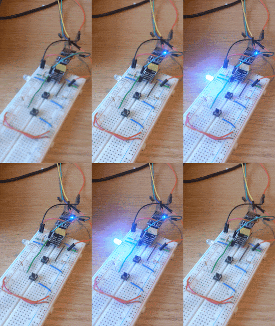
I2S is started and the buffers are filled with a runs of 0x00000000 and 0xFFFFFFFF. After programming the ESP8266 in the Arduino GUI, an LED can be hooked up to the data bit pin (GPIO3/RX0 - note you can't of course use this to receive serial UART data at this point). The result is a flashing LED (wow!) as the runs of 0s and 1s are thrown out of the data stream. We need to "yield()" every now and then to allow the ESP8266 to run background tasks, otherwise the watchdog will cause a reset. The outputDMA function is called every 3 seconds from the main loop.
Answer: Using DMA (Direct Memory Access) and to output to a GPIO using the I2S protocol of course!
Outputting memory straight to an LED using I2S
I2S (not to be confused with I2C!) is an audio protocol for transmitting data streams (link). Rather than other data transmission protocols where we are required to send data byte by byte, which might result in interrupted transmission, I2S allows us to stick a load of data in memory and the I2S hardware dutifully spits it out directly to a pin with no software intervention (hence Direct Memory Access). The data is packaged typically in 32-bits, comprised of 16-bits for the left audio channel, and 16-bits for the right audio channel. The protocol consists of three outputs; the data bits (SD), the data bit-clock (SCLK), and a signal (WS) that toggles every word of data, in order to tell the audio hardware to differentiate between the left and right data-stream.
The ESP8266 has built-in I2S hardware, meaning we can use the protocol to spit out a continuous datastream of whatever we desire! This has been used to great effect with an ESP8266 MP3 decoder (https://github.com/espressif/ESP8266_MP3_DECODER) and to creative ends to accurately control the timings for addressable WS2812b LEDs (https://electronut.in/nrf52-i2s-ws2812/)
The ESP8266 pins for I2S are:
Data bits (SD) = GPIO3/RX0
Data bit-clock (SCK) = GPIO15
Word select (WS) = GPIO2/TX1
Minimum code
What is the minimum code required for DMA I2S output? I took my cue from a discussion here. The code didn't work straight away but was easily corrected to work - it is important to check that the output buffers are not full and waiting (with a non_blocking call) until they are available for writing. Below is all the code we need to output data with the I2S protocol. In this example, the data rate is set (double words per second, rather than bits per second). Setting it to 10,000 here means that 10,000 * 32 bits are output per second (=320,000 bits/sec). In this example we are filling blocks of memory either with runs of 0x00000000 or 0xFFFFFFFF and toggling between them every 4096 double-words. As the double-word rate is set as 10,000, changing every 4096 double-words will give us a pin toggle every 0.4096 seconds. Because we are running the counter to 50,000, the flashing will last for 5 seconds.
I2S is started and the buffers are filled with a runs of 0x00000000 and 0xFFFFFFFF. After programming the ESP8266 in the Arduino GUI, an LED can be hooked up to the data bit pin (GPIO3/RX0 - note you can't of course use this to receive serial UART data at this point). The result is a flashing LED (wow!) as the runs of 0s and 1s are thrown out of the data stream. We need to "yield()" every now and then to allow the ESP8266 to run background tasks, otherwise the watchdog will cause a reset. The outputDMA function is called every 3 seconds from the main loop.
#include <i2s.h>
#include <i2s_reg.h>

#define write_sample(data) while (i2s_write_sample_nb(data)==0)

void setup()
{
    Serial.begin(115200);

    pinMode(3, OUTPUT); // Override default Serial initiation
    digitalWrite(3,0); // Set pin low
}

void loop()
{
    static unsigned long last = millis();
    if (millis() - last > 3000) {
      outputDMA();
      last = millis();
    }
}

void outputDMA(void)
{
   i2s_begin();
   i2s_set_rate(10000);

   uint8_t state=0;
   for (int i=0; i<50000;i++)
   {
    state = (i >> 12)%2; // Toggle every 4096 double-words
    if (state)
      write_sample(0xffffffff);
    else
      write_sample(0x00000000);

    if ((i % 1000) == 0) yield(); // without this get WDT resets
   }
   i2s_end();
}
How easy is that?! Easy-peasy, that's what! If we want to get a bit more flash (pun not intended), we can use a 5-bit fake pwm as below. In this case the LED is seen to glow. Clearly this is all somewhat overkill for something so simple, but with this minimal code framework it should be easy to output other interesting data streams...!
void outputDMA(void)
{
   i2s_begin();
   i2s_set_rate(50000); // Rate set to 50,000 lots of 32-bits per sec

   uint8_t pwm_index=0;
   for (int i=0; i<65536; i++) //(0 - (2^16-1))
   {
    pwm_index = i>>11;
    if (pwm_index>31) pwm_index = 63-pwm_index;
    if (pwm_index<0) pwm_index =0;

    write_sample(fakePwm[pwm_index]);

   if ((i % 1000) == 0) yield(); // without this get WDT resets
   }
   i2s_end();
}
UPDATE:
I have now used this I2S technique to send infra-red control signals accurately using the ESP8266, which coupled with Alexa control, enabled the creation of the voice-activated TV and projector control, the "IR-egg"!
Enjoy ESP8266 content? You might also enjoy:
Explore my other ESP8266 blog posts here
|


Is the entire data stream output handed without software intervention? Like in another thread? Or dedicated hw?
ReplyDeleteDoes the stream start with i2s_end()? How would you pause or stop it?
Hi there,
DeleteThe I2S streaming is handled by dedicated hardware, not threading. There is a small buffer that needs to be filled, using a non-blocking or blocking call. I2S hardware starts out putting the data buffers with i2s_begin(). The i2s_end() function STOPS the stream. There are no stop or pause functions implemented in the core functions as far as I know, but the buffers are small and you could stop writing samples to the I2S to implement this. The 16 most significant bits of the 32 bit sample are for the right channel and the other 16 bits are for the left channel. Check out the source code for more details:
https://github.com/esp8266/Arduino/blob/ec7644227ef19ebbf23a839154a878b7e9f7d577/cores/esp8266/core_esp8266_i2s.cpp
Can we control I2S LED flashing through web page by assigning button for it?
ReplyDeleteOf course! The ESP8266 is built for webpages so you have it serve a webpage and use that to control the led in whatever fashion you wanted!
DeleteOf course, please keep in mind that I used I2S to control an LED here as a teaching tool. It is a rather perverse way to do it in practical applications! I2S is typically used for audio streaming, not LED flashing!
DeleteHi, thanks for sharing. Could it be used to control/dimmer a 220V lamp with zero cross detection? Thanks a lot!
ReplyDeleteIt could be used as part of the solution, i.e. to provide a web interface for that control, but you would need additional circuitry. Firstly (and most importantly) you'll need to be competent with handling those voltages (they could kill you quite easily or burn your house down). Secondly you would need to know how the dimmer control is accomplished and how to provide that signal to the lamp in the correct way. Alternatively, a module like this might be useful:
Deletehttps://www.circuitar.com/nanoshields/modules/triac/index.html
You could use the ESP8266 to provide the control signal (shown with the green wire D3 in one of the figures). The I2S mode discussed in this post would be overkill, but you'd want some kind of PWM signal to control the module which the ESP8266 could provide. By the way, I found this module with a google search, I have no idea if they are safe or not. Again, if you don't know what you are doing, especially with mains voltages, don't do it! Hope that helps, Duncan
PS If you just want to switch the lamp on and off (without dimming control), you could just use a relay module (the same caveats about mains safety apply).
DeleteHi, thanks for sharing, Is there a way I can view the data inside the DMA buffer
ReplyDeleteIs it possible to make an optical I2S interface with port piping?
ReplyDeleteYes
Delete