Posts

Showing posts matching the search for label:Atmega328p|label:arduino|label:attiny85

Height and vertical velocity Kalman filtering on MS5611 barometer

Image
Height and vertical velocity from a MS5611 barometer Steps towards vertical flight control This isn't a post explaining how Kalman filters work, I assume some working knowledge.  Instead I wanted to record the process of developing a Kalman filter to derive both the height and the vertical velocity of a quadcopter using a MS5611 barometer, as it may be useful to others.  After recording some flight data on my quadcopter EEPROM, I then spat the output to a PC for post-processing and model training.  In Python I used a Kalman class to generate the following Kalman filter ( Wikipedia: Kalman filter ) based on the barometric height data.

Programming Atmega328p chip wirelessly with nRF24L01+ module - Part I

Image
I recently got my hands on a bunch of nRF24L01+ modules.  They're really easy to use and dirt cheap to pick up.  I followed this tutorial , which uses maniacbug's fantastic arduino library.  Although they are fairly ubiquitous as a radio transceiver of choice, I first heard about them on the excellent Julian Ilett's Youtube channel: I'm actually new to Arduino, but have messed about with programming chips and designing electronic devices for a couple of years.  I can see the attraction of Arduino, and I can see it's a great gateway for more fundamental electronics.  I picked up a couple of Arduino nanos (well, cheap Chinese knockoffs - they worked fine, incidentally), plugged them into the radios and installed some transmitting code on one (the joystick TX example in the  tutorial ) and some receiver code on the other - they worked great, out the box first time! Well that was just too easy!  The range was impressive too, at least twenty metres...

PCBs have arrived!

Image
Totally board A flurry of excitement this morning... The PCBs arrived from OSH Park!  I have to say they look gorgeous! I am in no way biased. As a quick sanity check of the custom USB part, I dropped in a USB socket and it fitted like a dream.  I can't wait to break out the soldering iron! Fingers crossed there aren't any absolute clangers in the board design!

Getting started with the Pro Micro Arduino Board

Image
This is a brief guide to getting started with the Pro Micro Arduino Board (Atmega32U4) - not to be confused with the Pro Mini (which utilises the Atmega328P)!  Note that the Pro Micro board comes in two flavours/flavors - 5V @ 16 MHz and 3.3V @ 8 MHz, so make sure you know which you have before getting started.  It should be indicated on the bottom silkscreen of the bottom, or you could take a voltmeter and measure VCC against GND - it will be either 5V or 3.3V.

Customising Optiboot

Image
I wanted to setup programming my custom Atmega328p board over Bluetooth.  Some have used the connection pin to control the Reset pin of the AVR.  However I want to use Bluetooth constantly, and only trigger a reset upon receiving a specific string sequence.  This requires tweaking the bootloader, using Optiboot as a basis: (1) Change Baudrate to be mutually compatible with Bluebooth and AVR. (2) Set an EEPROM byte in the main application, which could be read (and written) in the Optiboot routine. Setting up Optiboot in the Atmel environment: - Setup a project as usual in Atmel Studio - Copy files over from github to the project folder: optiboot.c, pindefs.h, stk500.h and boot.h. EDIT: It seems there is an AtmelStudio folder already set up on github . Setting baud rate to be compatible with AVR and Bluetooth module: 57600 bps - Insert #define BAUD_RATE 57600 (as required) into optiboot.c . - Compile and link project with following settings: Compiler Mis...

Clone wars

Image
Cloning Arduino core ... using TIMER0 in Arduino Sometimes you want to use TIMER0 in the Arduino IDE but default inclusion of Arduino libraries means that you can't have control over TIMER0 (it is used by millis() and delay() functions).  In a recent project, I wanted to use all the Atmega328 timers, and for various reasons, still use the Arduino IDE. The solution is simple .  Rather than hacking the core library, we'll clone the Arduino core library, define a board that uses the core library and then hack it to our specifications.  Steps: (1)  Clone the Arduino core Copy the Arduino core (C:\Program Files (x86)\Arduino\hardware\arduino\avr\cores) as "arduinohacked" -  the new core directory mustn't have an underscore in it! (2) Define a new board to use the cloned core library Open "C:\Program Files (x86)\Arduino\hardware\arduino\avr\boards.txt" and put the following text at the bottom.  This will define a new board in the Arduino IDE.  I...

Radio control

Image
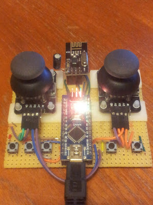
Accessing  quadcopter memory over radio The usual method of controlling quadcopters is to transmit a train of PPM signals from a radio transmitter, measure the length of the individual pulses on a microcontroller, via a radio receiver .  As part of my DIY ethos, and as a learning exercise, I have made the above controller with an nrf24l01 moduled and an Arduino Nano.  In a nutshell, the Arduino Nano captures the 2D joystick positions, used for yaw, throttle, pitch and roll, and the button presses.  A data packet is then sent by radio to the Quadcopter.  In fact there is a more powerful implementation going on.  What is interesting is how the controller sends data to the Quadcopter - it actually manipulates the memory directly on the Quadcopter AVR - how does it do that? Well, first of all the Quadcopter defines the memory addresses that the controller has access to by setting recording a pointer to the desired variable - note that the cast means...

Controlling my quadcopter with a PS2 controller

Image
I can now control my quadcopter with a PS2 controller - really cool!  The magic control box is powered either from the Arduino Nano inside and communicates with the quadcopter via radio, or a lipo battery, which is rechargeable over USB.  LEDs on the top feedback about the drone status and look really awesome. UPDATE: I have now incorporated the control electronics, and a long distance radio module directly into the PS2 controller!

HC-05 troubleshooting

Image
Some HC-05 modules are more equal than others I've been playing with some cheap HC-05 bluetooth modules I picked up off Amazon.  They are a very convenient and easy way to add remote control to a project, using two wire UART (RX/TX) in the usual way, so can replace an existing serial connection to a PC for example.  They work pretty much out the box and there are loads of guides to using them.  I thought I would share a few thoughts on using these modules though as I've come to realise that all HC-05s are not created equal... There are some visual clues.  On the back of my modules I have an "EN" pin whereas some other HC-05 modules have a "KEY" pin.  The KEY pin is used to place the module into "AT command mode", by putting it high (3.3V) before powering up the module.  I initially thought that the EN pin was analogous to the KEY pin (a different name perhaps), but the EN pin can be used to disable the bluetooth module , which I guess is...

Disassembling Arduino generated code

Image
Johnny Five... No disassemble! I recently had need to work out how many clock cycles certain functions in my code took to execute, so it was time to find the HEX file and disassemble back to the ASM instructions.  In the Arduino environment you are shielded from getting your hands dirty with the generated compiler files, but they can be located in a temporary directory in Windows, found under: C:\Users\ USERNAME \AppData\Local\Temp\build XYZ .tmp where " USERNAME " is your ... user name and XYZ is some long integer that Arduino comes up with.  Make sure you have recently compiled your code in Arduino - the folders are deleted or wiped when you exit Arduino.  In this folder you'll find some interesting files, among them the .HEX file and .ELF files are of particular interest.  Either make a .BAT file or use the CMD prompt to execute the following commands. Disassemble from HEX We'll use avr-objdump, but we need to specify the architecture.  Find ...

PS2 controller as a radio controller!

Image
Turning a PS2 controller into a wireless radio controller with Arduino Mini and an nRF24l01 radio module I have previously described a project to transmit PS2 controller signals by radio .  The project featured an Arduino Nano that read the PS2 signals and transmitted them with an nRF24l01 module.  Recently I have been inspired to incorporate the battery, charging circuit and Arduino right into the controller - heavily inspired by this project here:

Decoding 38 kHz IR signals with an Arduino Nano

Image
So... I have ambitions to use an ESP8266 board to control an IR LED and switch things on and off according to Alex voice control.  I have discussed how to implement Alexa voice control on an ESP-01S board here .  In this blog post I'll discuss how to grab, analyse and process an IR signal, ready to be re-transmitted.  In this case, I am using an TSOP4838 IR receiver, which takes an IR signal modulated at 38 kHz and demodulates to the corresponding 1s and 0s.  What is signal demodulation? This explains signal modulation excellently (stolen from SB-projects ):

Recovering ATMEGA328p chip from external clock fuse set

Image
A quick post of tragedy and triumph! Whilst breadboarding a new project with an Atmega328p chip (the heart of some of the Arduino ecosystem), I wanted to configure the AVR "fuses" (a desperately misleading term!) in order to use an external 16 MHz crystal, rather than the default internal 8 MHz oscillator.  This is straight forward and something I've done before.  Using the excellent fuse calculator , I wanted to get cracking and rushed in without double checking my fuse selection.  Big mistake!  I saw the option "external clock" (CKSEL=0000 SUT=00), and thought "great, that's it", also unselecting the CKDIV8 option (bit 7), generates the LOW fuse = 0xC0 and the HIGH fuse = 0xD9.  Two right mistakes here!  First of all the small one:  Selecting a box corresponds to setting the bit to '0', rather than '1', i.e. *unselecting/unticking* the CKDIV8 boxes will SET this bit as true (and divide the clock signal by 8).  It can't be...

4 x 16 bit servo control on Atmega328p

Image
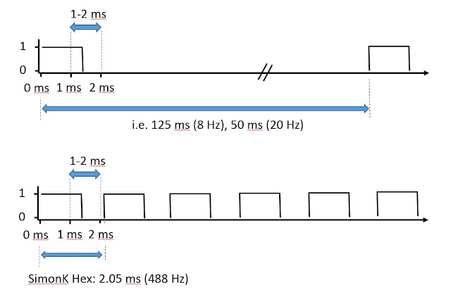
Controlling four motors with Atmega328 Timer1 One of the challenges in a quadcopter project is to correctly control the four thrust motors, via ESCs.  The control is effected by a pulse between 1-2 ms.  In ESC controllers, the refresh rate can be as low as 8 Hz or 20 Hz.  In quadcopters this refresh rate is far too slow - I have seen 100-200 Hz suggested as a suitable update frequency.  The "SimonK" hex is often reflashed to ESC controllers, as it has a refresh rate of approximately 488 Hz, very close to the theoretical refresh limit of just below 500 Hz. Algorithm idea Using the Atmega328 chip, we have only one 16-bit timer available, Timer 1.  Of course there are two other timers, but they are 8 bit timers, and I really want to stick to the resolution of the 16-bit timers.  We could consider using an AVR with four 16-bit hardware timers and use the four timer output pins, but it is interesting to see what can be done with just one.  So we ...

Programming Atmega328p chip wirelessly with nRF24L01+ module - Part II

Image
Fitting nRF24L01+ code into a bootloader A brief follow up to an earlier  post .  I previously had a system working whereby I was able to program an Atmega328p chip, using a connected Arduino Nano, but crucially using an nRF24L01+ module rather than a wired UART/PC connection.  What I really wanted however was to remove the Arduino Nano, and to program the MCU chip 'directly' by use of a bootloader with nRF24L01+ code to replace with the usual UART functionality.  I thought initially that I wouldn't be able to cram the radio module code into a bootloader, but in fact it wasn't too difficult.  I used Optiboot as a starting point and implemented bi-directional radio control within the bootloader.  I think it ended up being less than 1024 words (2048 bytes). I'm not an expert here - but I had to modify the compiler and linker parameters to get things to work: Compiler flags: -g -Wall -Os -fno-split-wide-types -mrelax Linker flags: -Wl,-section-s...

Sending IR remote control signals

Image
In my previous post , we looked at how to grab an 38 kHz modulated IR signal, analyse and process it. Now we'll look at a couple of different ways to transmit a modulated IR signal - first with an Arduino Nano, and then with an ESP-01S board. UPDATE: I have now used I2S to accurately transmit a modulated IR signal with the ESP8266 chip

DMP 6-axis processing

Image
Rock, Roll and Yaw... and Barometric pressure! A change to the Quadcopter design!  Previously I had MPU6050 on a GY-521 board (acc+gyro) and the magnetometer HMC5883L on a GY-271.  I decided I wanted to have a barometer on the flight board for height control.  A bit of research revealed the MS5611 was a pretty sensitive standard barometer.  There wasn't room to add a separate barometer module to the flight control board and in fact it was cheaper to replace the GY-521 and GY-271 board with a single board, GY-86, that contained the accelerometer, gyroscope, magnetometer and barometer!  On this single board we have the MPU6050 accelerometer and gyroscope, magnetometer HMC5883L and barometer MS5611. Calculating quadcopter orientation So I'm using the GY-86 10 DOF board to calculate the orientation of the quadcopter.  We have the MPU6050 processing chip on board, and although we can read off the various sensors readings, a technology/software ...