Posts

MAR and memory

Image
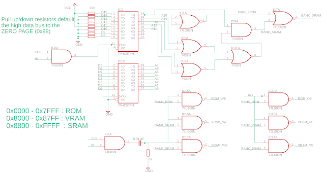
Memory Address Register (MAR) and Memory Memory is (obviously) an essential part of a computer, and this blog post is part of a series and concerns adding different types of memory to my 8-bit computer . The memory of my 8-bit computer is addressed with a 16-bit address register, which gives access to 64k of memory.  I have divided this memory space into ROM (EEPROM), VRAM (for the LED WS21812b module ) and SRAM, with the following memory divisions: 0x0000-0x7FFF: ROM 0x8000-0x87FF: VRAM 0x8800-0xFFFF: SRAM A zero-page in SRAM can be accessed at 0x8800-0x88FF.  In terms of the electronics, this is achieved by not writing to the high databus (D8-D15), and instead letting a set of pull up and down resistors set the high databus to 0x88 by pulling D15 and D11 high, and D14-12 and D10-8 to ground.  By not writing "0x88" explicitly to the high databus, instructions that access this memory are quicker than they otherwise would be.  The address decoding logic is fairly straightforwa

8-bit Computer: ALU

Image
With an "A" and "B" register in place for my 8-bit computer , I need to implement an Arithmetic Logic (ALU).  The ALU is the part of the computer where the interesting stuff happens - data is manipulated in some way, i.e. where the computer actually COMPUTES!  Ben Eater uses 2 x 74LS283 4-bit addition ICs in his ALU to perform 8-bit addition of an A and B register, and uses a control signal and some glue logic to implement subtraction by way of 2s complement addition .  Flags are then set based on the outcome of the ALU, and the program can branch (or not).  I considered a similar implementation with 74LS283 chips, but also adding some logic gate, i.e. an 8-bit NAND or NOR function to construct different logic functions.  The outputs from the addition/subtraction section and the NAND/NOR logic section would then need to be multiplexed to select the output of interest and latched into the flag register which I decided not to hav

8-Bit Computer: WS2812B LED module

Image
Every 8-bit computer needs some kind of output display, whether this is a LCD display, or a 7-segment display, it needs some way of displaying data to the outside world.  Wouldn't it be cool to have a pretty RGB LED display as a way of not only showing the output of computation, but to act as a screen for showing animations, even playing simple games?  At the very least it would be cool to have a kind of "RAM visualizer" to show the contents of RAM for debugging purposes. With that in mind, I recently came across a post on the timing for WS2812 LEDs, part 1 and part 2 , in which the blog post author Tim sets out the limits of the WS2812 LED protocol and shows they are rather flexible and not as stringent as the official datasheet suggests (i.e. see here for WS2812b datasheet or here ). Further he suggests a way of controlling LED strips with a simple timing cycle, encoding either a 0 or a 1 bit, like so: Tim then goes on to write some assembly language to control WS2812

8-bit Computer: Adding the UART modules

Image
Until now, my UART transceiver module existed across three breadboards and was not integrated into the 8-bit computer, see  previous post .  I have now added my UART module to the 8-bit breadboard computer I am building.  I have modified the design slightly by adding an 74LS245 so that the received byte can now be put out onto the databus.  The blue LED bar below shows the current received byte, and the green LED is lit when    Updated schematic The UART TX module remains as previously  described, but the finalised UART RX schematic is updated below.  Notably a 74LS245 chip can now control the output onto the databus. The RX_READY signal of the UART RX module will feed into the status byte (flag register) of the computer, along with the ALU flags and the SENDING bit of the UART TX module. Chip geography In terms of placement of the chips to make as logical and clean layout as possible, I have used the following layout below.  The transceiver spans 2 breadboards, and borrows an AND gat

8-bit Computer: A & B registers and LED outputs

Image
This is part of a series on the build of my 8-bit computer .  Registers and LED outputs Registers are an essential part of a CPU.  In my 8-bit computer build, I want to sneak in as many LEDs ( blinkenlights ) as possible to indicate the 8-bit values held in various registers, not only useful for debugging but also because it looks friggin' cool.  For my A and B registers, which will feed into the ALU, I'm using a 74LS245 as an output latch, and the 74LS377 D-type flip-flop to set the value of the register.  Note that the 74LS377 is an 8-bit version of the 4-bit 74LS173, which I would have to use two of to have an 8-bit register.  The schematic for each register is pretty straightforward, see below: For the LED output, I decided to use these LED bar displays with a 220 Ohm SIL resistor pack.  To save on breadboard space, I decided to try and fit both the A and B register on the same breadboard, along with an LED bar displays for each register.  With the 4 ICs and the 2 LED bar d

8-Bit Computer: Clock Module with Breakpoints

Image
Every 8-bit computer needs a clock module and here is mine.  It is heavily influenced by the Ben Eater clock module , but with some changes.  Firstly, what's the same?  The clock features two 555 clocks, one clock uses an astable 555 configuration and the second clock uses a monostable configuration for single clock stepping.  A third 555 implements a bistable configuration which acts as a selector between the two clocks.  I didn't have a SPDT switch, so used two push buttons instead, which works fine.  The circuitry for the 555s are shown on the top line of the circuit diagram at the bottom of the post. So what's different with my implementation of this clock module?  Firstly, regarding the logic for clock selection. I replaced the AND, OR and NOT logic gates that Ben uses with just NAND logic gates.  This was driven by a desire to use fewer ICs and because I didn't have any OR chips to hand!  In fact, if you just want to select between the clock source without a HALT

IoT Home Power Monitor with two components (and an ESP8266)

Image
I was looking at my electricity meter the other day when I noticed a red LED flashing every so often.  Looking closer I saw that it flashed for every 1/1000 of a kWh of electrical energy consumed.  Quite quickly I was running over the house, switching on various electrical items in different combinations, and counting roughly how many seconds between the red LED pulses.  Clearly the faster the flashing LED, the more quickly electricity is being used.  I was excited (because I get excited about such things), that I could potentially measure my electricity usage in real time by just watching this LED pulse.  From here it would be a snap to post this data to a server and provide remote domestic logging of power usage. I decided to use an ESP8266 NodeMCU (ESP-12E) as a powerful microcontroller to time the intervals, and very simple way of connecting to my home WiFi.  The light detection circuit is below and is embarrassingly simple: one light-dependent resistor, one resistor (1 MOhm, more

8-Bit Computer: UART Transceiver for breadboard computer

Image
You art UART I have an increasing fascination with building 8-bit computers from TTL chips, sparked by the excellent Ben Eater series on YouTube , and deepened by a variety of examples on Hackaday .  In the process of designing/building my own 8-bit computer, I wondered how easy it would be to implement a UART transceiver purely out of basic 7400 series ICs...    The finished design: UART Transceiver built from 7400 series ICs. 

SN76489 Arduino MIDI player

Image
I've been thinking about retro 8-bit computers recently and came across the audio chip SN76489  ( datasheet ), which has been used in the BBC Micro , Sega Genesis and Master System (among many others ).  The chips are capable of generating 3 independent frequencies simultaneously, as well as a 4th channel for noise.  They seemed easy enough to interact with, using a write pulse to load commands into the chip in a parallel-fashion.  I thought it would be fun to hook one up to an Arduino and play some retro game MIDI files through them!  It would be easy to take a few and make a MIDI synthesizer out of them too. All code for this project can be found at my Github here:  https://github.com/shepherdingelectrons/SN76489_player It's easy to pick up a few cheaply from the usual sort of places, so I bought a pack of 5, and then had a read through the datasheet , which is always fun!

Assembler for Ben Eater's 8-bit computer

Image
I've been thinking about 8-bit computers recently and came across the most excellent breadboard 8-bit computer series by Ben Eater .  Absolutely terrific stuff, fantastic break down of the subject and a clear and talented educator.  Like many, it got me pondering building my own 8-bit computer, modifying the original design to my specifications and writing custom opcodes and microcode.  Thinking about how to convert assembly language easily to machine code for such a custom computer, I wondered if there were any assemblers out there for assembling custom ASM.  It turns out there are, and the one I've been playing with is called... customasm .

EAGLE useful tips

Image
Eagle is a pretty useful piece of software for designing circuit schematics and PCBs.  I don't use it often enough to get really good at it however, and there are certain things in Eagle that I find myself having to "google" every time I want to do it!  So without further ado, this is my growing list of Eagle tips, in no particular order:

ATtiny Mario handset

Image
This is part 2 of my ATtiny Mario project - part one is here  -  a Mario-type game I made for the ATtiny85 AVR as a fun way of learning about the chip.  After writing the software, I decided I wanted a nice housing for the mass of wires on my breadboards and thought it would cool to put it into a NES-style controller, which is what this post will discuss.

ESP8266 low power DHT11 temperature and moisture remote sensor

Image
I have a problem with moisture in my loft.  After planning some intervention, I wanted a way to remotely monitor the humidity and temperature up there, and to visualise the data on a server.

ATtiny Mario

Image
ATtiny85 Mario Challenge! The ATtiny85 microcontroller is a capable but compact AVR.  However with only 8K of program memory, 512 bytes of EEPROM, 512 of SRAM and only 8 pins (3 of which are dedicated to the usual suspects of Vcc, GND and RESET), it best suited to performing tasks where memory demands are not large, and only a few pins are required for interfacing.